Key Takeaways • The Event: XL-C1860P5S11-62C3C1 delivers up to 15W power at 1500mA in a compact 1.8×6.0mm 1860 ceramic package. • The Cause: Flip-chip architecture and low thermal resistance (3–5°C/W) enable high luminous flux (1000–1500 lm) under automotive conditions. • The Implication: Proper thermal design, bin control, and MSL3 handling are critical for OEM-grade reliability and yield stability.
📌 Opening High-current mid-size LEDs are increasingly replacing multi-emitter arrays in automotive and industrial lighting. The XL-C1860P5S11-62C3C1 positions itself as a 15W-class 1860 ceramic flip-chip solution. This article evaluates its electrical, thermal, and process implications for OEM and EMS teams.
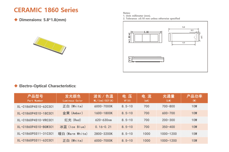
🔍 What’s Changing The device operates at a maximum forward current of 1500mA, with pulse capability up to 2000mA. At 1000mA, typical forward voltage ranges from 8.7V to 9.6V, delivering 1000–1500 lm depending on bin selection .
Key structural characteristics include: • 1.8 × 6.0 × 0.7 mm ceramic SMD footprint • Flip-chip technology (no traditional wire bonding stress points) • Viewing angle: 120° • CCT range: 5500K–7000K • CRI: Ra 70 • Thermal resistance (Rth j-s): 3–5°C/W
Operating temperature spans –40°C to +135°C, aligning with automotive-grade environmental requirements .
📊 Data and Performance Comparison
Electrical Performance at IF = 1000mA: • Forward Voltage: 8.7–9.6V • Luminous Flux: 1000–1500 lm • Junction Temperature Limit: 145°C • ESD Protection (HBM): 2000V
Brightness Binning (IF=1000mA): • N5: 1000–1100 lm • N6: 1100–1200 lm • N7: 1200–1350 lm • N8: 1350–1500 lm
Voltage Binning: • S13-3: 8.7–9.0V • S13-4: 9.0–9.3V • S13-5: 9.3–9.6V
For procurement teams, bin discipline directly impacts driver compatibility and optical uniformity in multi-LED systems.
⚠️ Why Old Assumptions No Longer Work Legacy 2835/3030 assumptions—lower drive current, higher driver flexibility, and relaxed PCB thermal design—do not translate to 15W-class 1860 devices.
At 1500mA, thermal headroom narrows significantly. With Rth j-s at 3–5°C/W, even small interface resistance increases can push junction temperature toward its 145°C ceiling .
Additionally: • MSL Level: 3 (controlled floor life required) • Reflow limited to two cycles • Recommended max welding temperature: 240±5°C for 6s
Ignoring these process constraints directly increases latent field failure risk.
🏭 Implications for OEM / EMS / Procurement Thermal Stack Design The datasheet recommends increasing copper area on the intermediate pad or connecting it to the negative pad to improve heat dissipation . Copper substrates with thermoelectric separation are suggested for higher power applications.
Driver Architecture The LED must be driven by a constant current source. Use of constant voltage drivers requires explicit risk evaluation .
Moisture Control After opening, devices must be used within 168 hours at ≤30°C and ≤40% RH. Baking conditions are specified at 60±5°C for 24 hours if moisture exposure occurs .
Reliability Qualification The component undergoes: • 1000-hour high-temperature storage (85°C) • 85°C / 90–95% RH humidity testing (240h) • 100-cycle thermal shock testing
For EMS partners, these standards align with automotive validation flows but require disciplined process control to maintain consistency.
🚀 How Smart Teams Are Responding 1.Thermal Simulation First Engineering teams are modeling full stack-up (MCPCB + TIM + heatsink) before BOM freeze to ensure junction margin below 120°C in worst-case ambient. 2.Tight Bin Procurement Strategy Forward voltage and brightness bin harmonization reduces driver redesign risk and field color mismatch. 3.Controlled Reflow Profiles Strict adherence to lead-free reflow peak 255°C (+0/–5°C) and ≤2 cycles prevents encapsulation stress . 4.ESD Governance With 2000V HBM tolerance, factory grounding and wrist-strap compliance remain mandatory, especially in high-throughput SMT lines .
🔚 Closing The XL-C1860P5S11-62C3C1 represents a compact 15W-class solution capable of replacing multi-emitter arrays in automotive and industrial platforms. Its performance advantages are clear—but only when matched with disciplined thermal engineering, bin strategy, and moisture control.
For OEM and EMS teams building next-generation lighting platforms, resilience begins at the component physics level. Reach out to discuss system-level reliability planning.