📌 Product Overview
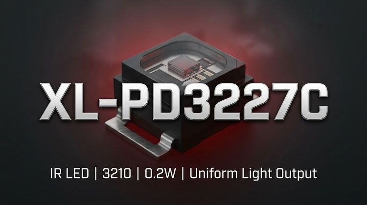
The XL-PD3227C from XINGLIGHT is a compact infrared receiver diode packaged in a 3.2 x 2.7 x 1.0mm form factor, utilizing a transparent colloid optimized for 940nm peak wavelength detection. 💡 It is engineered for high efficiency and fast startup, making it suitable for SMT integration in environments requiring precise photoelectric conversion.
This component is specifically designed to support stable performance in consumer electronics and industrial sensing applications. 🔒 The design focus is on providing reliable infrared signal reception while maintaining a low profile suitable for modern, space-constrained circuit boards.
🚀 Typical Applications
Based on its spectral sensitivity and electrical characteristics, the XL-PD3227C is deployed in scenarios requiring specific infrared detection capabilities:
- Consumer Electronics: Infrared remote controllers for Set-Top Boxes (STB), TVs, and air conditioning systems.
- Industrial Automation: ⚙️ Usage in counters, infrared photoelectric switches, and smart metering systems.
- ** Surveillance:** Integrated into camera monitoring heads for signal reception.
- Robotics: Intelligent cars and robotic sensor arrays for obstacle detection or communication.
- Medical Devices: Non-invasive medical equipment requiring precise light sensing.
- Wireless Systems: Short-range wireless communication and signal transmission modules.
📉 Key Technical Specifications
The performance of the XL-PD3227C is defined by its optoelectronic characteristics under standard test conditions (Ta=25°C). The following table outlines the representative values critical for circuit design calculations.
| Parameter | Symbol | Test Condition | Representative Value | Unit |
|---|---|---|---|---|
| Peak Sensitivity Wavelength | λp | -- | 940 | nm |
| Spectral Bandwidth | λ0.5 | -- | 400 ~ 1100 | nm |
| Reverse Light Current | IL | λp=940nm, VR=5V, Ee=1mW/cm² | 6.5 | μA |
| Open-Circuit Voltage | VOC | λp=940nm, Ee=5mW/cm² | 0.41 | V |
| Short-Circuit Current | Isc | λp=940nm, Ee=1mW/cm² | 6.5 | μA |
| Total Capacitance | Ct | VR=5V, f=1MHz | 6.0 | pF |
| Response Time | Tr / Tf | VR=10V, RL=1kΩ | 10 | μs |
💡 Note: The low total capacitance (6pF) and fast response time make this component suitable for high-frequency carrier signal processing.
🔒 Absolute Maximum Ratings & Process Limits
To ensure reliability and prevent catastrophic failure during operation or assembly, the following limits must not be exceeded. These ratings are critical for stress testing and robust design validation.
| Parameter | Symbol | Maximum Rating | Unit | Notes |
|---|---|---|---|---|
| Power Consumption | Pd | 150 | mW | |
| Reverse Voltage | VR | 32 | V | |
| Operating Temperature | Topr | -20 to +85 | °C | Ambient temperature range |
| Storage Temperature | Tstg | -40 to +85 | °C | |
| Soldering Condition | Tsol | 260 | °C | ≤ 6 Seconds (Max) |
| Reverse Breakdown Voltage | BVR | 32 (Min) / 170 (Typ) | V | IR=100μA |
⚠️ Warning: Exceeding the Reverse Voltage (VR) of 32V or the Power Consumption (Pd) of 150mW may cause irreversible damage to the diode junction. For wave soldering, the recommended peak temperature is controlled at 240°C for 6 seconds to mitigate thermal stress.
📦 Package, Dimensions & Assembly Notes
The XL-PD3227C utilizes a standard 3210 SMD package (3.2mm x 2.7mm x 1.0mm). The product follows EIA standard packaging specifications, ensuring compatibility with automated pick-and-place machinery.
Physical & Process Specs:
- Dimensions: 3.2 (L) x 2.7 (W) x 1.0 (H) mm. Tolerances are ±0.30mm unless noted.
- Moisture Sensitivity: Classified as MSL Level 3. Proper baking before reflow is required if the moisture barrier bag has been breached.
- Soldering Profile: 🛠️ It is recommended to perform reflow soldering only once. Do not apply mechanical stress or pressure to the component during heating. Ensure the PCB does not warp post-soldering to prevent cracking the die.
- Repair: Avoid soldering iron repair after initial mounting. If unavoidable, use a double-head soldering iron (<300°C, <3 sec per terminal).
🤝 Sourcing & Supply Considerations
When integrating the XL-PD3227C into production, consider the following supply chain factors:
- Authenticity Verification: Procure through authorized channels to ensure compliance with ROHS directives and MSL 3 packaging standards.
- Sample Evaluation: Request samples for binning verification to validate sensitivity (IL) consistency across different batches for mass production.
- Inventory Management: 📈 Check lead times for the 3215/3227 form factor, as similar package sizes are often in high demand.
- Cross-Reference: Verify pin compatibility (1: Cathode, 2: Anode) when considering drop-in replacements.
❓ Frequently Asked Questions
Q: What is the recommended soldering temperature for the XL-PD3227C to avoid damage?
A: The datasheet recommends a maximum welding temperature of 240°C for 6 seconds. For manual soldering, the iron tip temperature should not exceed 300°C, with contact time limited to 3 seconds per terminal.
Q: Can this component be used for high-speed infrared data transmission?
A: Yes, with a rise and fall time (Tr/Tf) of approximately 10μs and a low total capacitance of 6pF, it is suitable for standard remote control protocols and moderate-speed data transmission.
Q: What are the storage requirements to prevent moisture damage?
A: The XL-PD3227C has a Moisture Sensitivity Level (MSL) of 3. It should be stored in a dry environment (< 60% RH) or within its anti-static moisture-proof bag. If exposed to ambient air for more than 168 hours, baking is required prior to reflow soldering.
Q: How does the spectral sensitivity impact the choice of emitter?
A: The diode has a peak sensitivity wavelength (λp) of 940nm. For optimal signal integrity, it should be paired with an infrared emitter LED that operates at the same 940nm wavelength.
Q: Is the XL-PD3227C ROHS compliant?
A: Yes, the datasheet specifies that the environmental protection process complies fully with the ROHS Directive.