📌 Product Overview
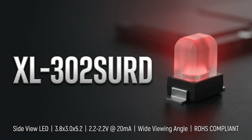
The XL-302SYGD is a standard F3 (3mm) radial LED from XINGLIGHT, featuring a green colloid and a dominant wavelength of 570nm. It is engineered primarily for through-hole PCB assembly (THT) in status indication and backlighting scenarios. 💡
💡 Design Focus: This component balances luminous intensity (up to 300mcd) with low power consumption (70mW max). It is suitable for general indication in consumer appliances, automotive interiors, and industrial control panels.
🔌 Typical Applications
Based on its robust operating temperature range (-20°C to +85°C) and moisture sensitivity level, the XL-302SYGD is optimized for the following use cases:
- Consumer Electronics: Status indicators for home appliances and digital devices.
- Automotive Electronics: Dashboard illumination and interior signaling (non-critical).
- Industrial Instrumentation: Indicator lights for power supplies and communication equipment.
- Urban Lighting & Decorations: Accent lighting in architectural or signage applications.
- Educational & Medical Toys: Low-voltage indicators requiring safe DC drive.
📊 Key Technical Specifications
⚠️ Note: Performance values are measured at Ta=25°C.
| Parameter | Symbol | Min | Typ | Max | Unit | Test Condition |
|---|---|---|---|---|---|---|
| Luminous Intensity | Iv | 50 | - | 300 | mcd | IF = 20mA |
| Dominant Wavelength | λd | 562 | 570 | 575 | nm | IF = 20mA |
| Peak Wavelength | λp | - | 570 | - | nm | IF = 20mA |
| Forward Voltage | VF | 1.8 | 2.2 | 2.6 | V | IF = 20mA |
| Viewing Angle | 2Ø1/2 | - | 30 | - | deg | IF = 20mA |
| Reverse Current | IR | - | - | ≤10 | μA | VR = 5V |
⚡ Absolute Maximum Ratings & Process Limits
Exceeding these ratings may cause device failure or permanent damage. 👇 Design margins must account for these limits to ensure yield rate and reliability.
| Parameter | Symbol | Max Value | Unit | Notes |
|---|---|---|---|---|
| Power Dissipation | Pd | 70 | mW | Derate above 25°C ambient |
| Continuous Forward Current | IF | 20 | mA | |
| Peak Forward Current | IFp | 80 | mA | Pulse width ≤ 10ms, duty ≤ 1/10 |
| Operating Temperature | Topr | -20 ~ +85 | °C | |
| Storage Temperature | Tstg | -40 ~ +85 | °C | |
| Soldering (Wave) | Tsol | 240 | °C | ≤ 6s |
| Soldering (Manual) | Tsol | 300 | °C | ≤ 3s, >2mm from body |
📦 Package, Dimensions & Assembly Notes
- Package Type: F3 Radial Lead (Diffused).
- Dimensions: 3.8 x 3.0 x 5.2 mm (Body), Lead length 18mm.
- Moisture Sensitivity: MSL Level 2 (Must be used within 1 year of opening if not baked).
- Assembly: Designed for wave soldering or manual soldering. Ensure the soldering point is >2.0mm from the colloid bottom to prevent thermal damage.
- Tolerance: General dimensional tolerance is ±0.50mm unless noted.
🚀 Sourcing & Supply Considerations
- Binning Codes: Verify brightness (A1-A3) and voltage (N12-7 to N13-1) codes to match circuit design limits.
- Authenticity: Source through XINGLIGHT authorized channels to avoid counterfeit components with inconsistent wavelength or thermal performance.
- Packaging: Supplied in EIA standard compliant bags with moisture-proof and anti-electrostatic foil.
❓ FAQ
Q: What is the difference between the A1, A2, and A3 brightness codes? A: These codes refer to the Luminous Intensity (Iv) binning. A1 ranges from 50-100 mcd, A2 from 100-200 mcd, and A3 from 200-300 mcd at 20mA. Selecting the correct bin ensures visual consistency across your product's LED array.
Q: Can this LED be used in outdoor applications? A: While the operating temperature supports a wide range, the IP rating of the final product depends on the enclosure design. The component itself is not waterproof; it requires a protective housing for outdoor or high-humidity environments.
Q: What are the storage requirements to prevent damage? A: The XL-302SYGD has an MSL of 2. If the moisture-proof bag is opened, the components should be soldered within 1 year (floor life). For storage exceeding this, baking may be required to prevent popcorning during soldering.
Q: Is the forward voltage drop critical for my battery design? A: Yes. The VF ranges from 1.8V to 2.6V. If driving multiple LEDs in series or from a low-voltage source (e.g., 3V battery), you must select the specific voltage bin (e.g., N12-7 for 1.8-2.0V) to ensure current regulation and brightness stability.
Q: How close can the solder joint be to the LED body? A: The datasheet specifies a minimum distance of 2.0mm from the bottom of the colloid to the soldering point. Closer soldering risks thermal damage to the epoxy and internal bond wires.