📦 Product Overview
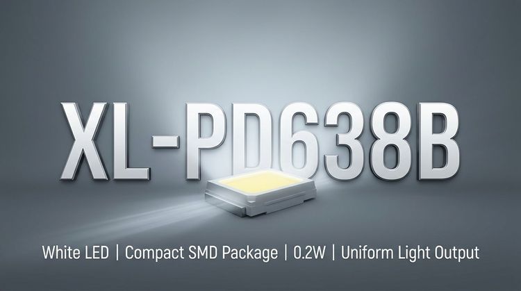
The XL-PD638B is a 940nm infrared receiving photodiode in a through-hole package, designed for optical signal detection in control and communication systems. It targets applications requiring stable IR response and moderate-speed detection.
The real design focus lies not in peak wavelength alone, but in balancing sensitivity (IL), response time (~50µs), and noise (dark current), especially under varying ambient conditions.
🚗 Typical Applications
Infrared remote control receivers
Optical switches and proximity sensing modules
Industrial counters, smart meters, and automation nodes
Security cameras and monitoring heads
Wireless signal transmission (IR-based links)
Robotics and smart vehicle navigation systems
📊 Key Technical Specifications
Parameter Value / Range Notes
Peak Wavelength (λP) 940 nm Standard IR remote frequency
Spectral Range 840 – 1100 nm Broad IR detection window
Reverse Light Current (IL) 15 – 25 µA (typ.) Key sensitivity metric
Dark Current (ID) 5 – 30 nA Impacts noise floor
Rise / Fall Time 50 µs / 50 µs Limits modulation speed
Capacitance (Ct) 25 pF Affects bandwidth
Open Circuit Voltage 0.35 V Under defined irradiance
📌 Engineering Insight:
The IL binning (10.2–33 µA across bins) introduces variability that directly affects receiver gain design and detection thresholds—critical in multi-source procurement.
⚠️ Absolute Maximum Ratings & Process Limits
Parameter Limit Design Impact
Power Dissipation 150 mW Thermal margin constraint
Reverse Voltage (VR) 32 V Must avoid breakdown region
Operating Temp -40°C ~ +85°C Industrial-grade baseline
Storage Temp -40°C ~ +85°C Logistics compatibility
Soldering Temp ≤260°C / 6s Wave solder profile limit
📌 Risk Note:
The breakdown voltage range (32–170V) indicates wide process variation—designers should not rely on typical values for protection design.
📐 Package, Dimensions & Assembly Notes
Package: Through-hole epoxy (black IR filter)
Size: 7.6 × 5.25 × 2.75 mm
Lead Length: ~13.5 mm
Polarity: Defined (Anode/Cathode marked)
Tolerance: ±0.30 mm
📌 Assembly Considerations:
MSL Level 3 → requires moisture control before reflow
Lead forming must occur ≥2 mm away from resin body
Avoid mechanical stress during soldering and cooling
Recommended wave solder (single pass)
📌 Process Risk Insight:
Epoxy package fragility + manual soldering constraints (<300°C, <3s) increase field failure risk if rework is frequent.
🔗 Sourcing & Supply Considerations
Bin-based sensitivity (IL) requires strict incoming inspection alignment
Through-hole format suits legacy designs but limits SMT migration
MSL 3 implies storage and baking control for global EMS operations
Verify labeling (LOT / BIN / IL rank) to prevent mixed-batch performance drift
For cross-reference, matching λP=940nm alone is insufficient—response time and capacitance must align
❓ FAQ
Q1: Is XL-PD638B suitable for high-speed IR communication?
A: Not ideal. With ~50µs response time, it fits low-to-mid speed signaling rather than high-frequency modulation.
Q2: What is the key parameter for sensitivity comparison?
A: Reverse light current (IL). However, bin variation must be considered in production.
Q3: Can it replace standard 940nm photodiodes directly?
A: Only if capacitance (~25pF), response time, and package footprint match system requirements.
Q4: What is the main noise concern?
A: Dark current (ID), especially at higher temperatures, affects signal detection thresholds.
Q5: Any SMT alternative concerns?
A: Yes. This is a through-hole device—migration to SMD requires optical alignment and PCB redesign.