🔍 Product Overview
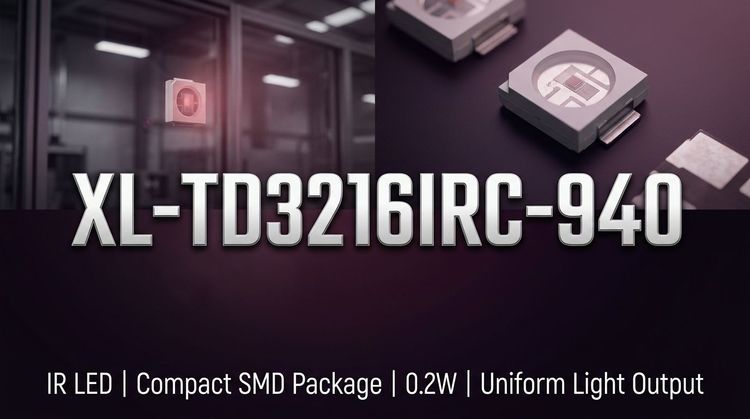
The XL-TD3216IRC-940 is a 1206 package (3.2×1.6×1.96 mm) surface-mount infrared emitting diode designed for 940 nm IR transmission in compact optoelectronic systems. It is typically paired with phototransistors for reflective or transmissive sensing architectures.
The real design challenge lies in managing radiation intensity distribution, angular emission, and bin consistency, rather than simply selecting a nominal wavelength.
📡 Typical Applications
This emitter is used in IR systems where controlled emission geometry and wavelength compatibility are required:
- IR photoelectric switches and object detection modules
- Infrared light barriers and slot sensors
- Smoke detectors and environmental monitoring devices
- Consumer electronics (gesture sensing, remote control systems)
- Paired emitter-receiver systems (e.g., with 880–940 nm phototransistors)
👉 Especially relevant for systems requiring 940 nm low-visible signature emission, reducing red glow leakage.
⚙️ Key Technical Specifications
| Parameter | Value | Notes |
|---|---|---|
| Package | 1206 (3.2×1.6×1.96 mm) | Dome lens structure |
| Dominant Wavelength | 940 nm | Standard IR band |
| Radiant Intensity | 15–30 mW/sr | IF=20 mA |
| Viewing Angle | 30° | Half-angle (2θ1/2) |
| Forward Voltage | 1.2–1.5 V | IF=20 mA |
| Reverse Current | ≤1 μA | VR=5 V |
| Spectral Width | ~40 nm | Narrow emission band |
Engineering Insight:
- The 30° viewing angle defines optical alignment tolerance—critical in light barrier designs.
- Intensity binning (P1-5 to P1-7) introduces up to 2× radiant variation, impacting sensing distance.
⚠️ Absolute Maximum Ratings & Process Limits
| Parameter | Limit |
|---|---|
| Power Dissipation | 50 mW |
| Forward Current (IF) | 30 mA |
| Peak Forward Current | 100 mA (pulse) |
| Reverse Voltage | 5 V |
| Operating Temperature | -40°C to +85°C |
| Reflow Soldering | 260°C / 6 s |
Design Constraint:
- Pulse operation (≤0.1 ms, duty ≤10%) enables higher peak output, but must be tightly controlled in driver circuits.
- Thermal derating (see page 6 curves) shows output drop at elevated temperatures—affects detection margin.
📦 Package, Dimensions & Assembly Notes
| Feature | Description |
|---|---|
| Package Type | 1206 SMD LED with lens |
| Dimensions | 3.2 × 1.6 × 1.96 mm |
| Lens Type | Transparent epoxy dome |
| Pad Layout | Standard 2-pad SMT |
| Tolerance | ±0.25 mm |
Assembly considerations:
- Lens structure improves forward intensity but increases sensitivity to mechanical stress during reflow (see page 11).
- Recommended peak soldering temperature is 240±5°C for 6s, tighter than generic limits.
- Ultrasonic cleaning must remain below 300W to prevent internal damage.
🔗 Sourcing & Supply Considerations
- Lock radiant intensity bin (P-code) and wavelength bin (IR02–IR04) to ensure system consistency.
- Verify forward voltage bin (N17-x) to maintain driver compatibility across batches.
- Ensure MSL3 handling compliance—open time limited to 168 hours.
- For second sourcing, match optical geometry (view angle + lens), not just wavelength.
❓ FAQ
Q1: Why choose 940 nm instead of 850 nm?
A: 940 nm minimizes visible red glow, making it suitable for consumer and security applications requiring low visibility.
Q2: What defines detection distance?
A: Primarily radiant intensity bin and receiver sensitivity—not just nominal IF current.
Q3: Can it be overdriven in pulse mode?
A: Yes, up to 100 mA peak, but only under strict pulse width and duty cycle limits.
Q4: What is the main mismatch risk in pairing?
A: Spectral mismatch and angular misalignment between emitter and receiver.
Q5: Is it interchangeable with other 1206 IR LEDs?
A: Mechanically yes, but optical performance (angle, intensity bins) must be validated.
```