📌 Product Overview
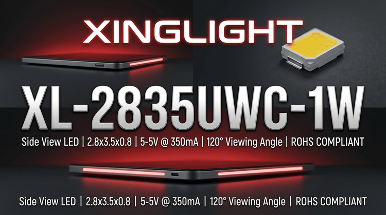
The XL-2835UWC-1W from XINGLIGHT is a high-performance 2.8mm x 3.5mm SMD LED designed for 1W power applications. 💡 It delivers a luminous flux of 100-130 lm with a cool white color temperature range (6000K-7500K), making it ideal for high-density lighting arrays.
Target applications primarily include indoor and commercial lighting, such as light tubes, downlights, and backlighting. ⚡ Real design focus must be placed on thermal management and binning selection to ensure consistent color and output in mass production.
🚀 Typical Applications
Based on the model's 120° viewing angle and 350mA drive current, the XL-2835UWC-1W is best suited for:
- Indoor Lighting: Fluorescent tubes, residential light strips, and downlights requiring uniform illumination.
- Commercial Display: Illuminated advertising signs, light boxes, and channel letters.
- Backlighting: LCD panels requiring bright, efficient light sources.
- Decorative Lighting: Flexible light strips where low profile (0.8mm height) is critical.
📊 Key Technical Specifications
💡 To ensure design compatibility, refer to the typical optical and electrical parameters under standard test conditions (Ta=25℃).
| Parameter | Symbol | Min. | Typ. | Max. | Unit | Test Conditions |
|---|---|---|---|---|---|---|
| Luminous Intensity | Φ | 100 | — | 130 | LM | IF = 350mA |
| Color Temperature | TC | 6000 | — | 7500 | K | IF = 350mA |
| Forward Voltage | VF | 2.8 | — | 3.4 | V | IF = 350mA |
| Viewing Angle | 2θ1/2 | — | 120 | — | Deg | IF = 150mA |
| Reverse Current | IR | — | — | 5 | μA | VR = 5V |
⚠️ Absolute Maximum Ratings & Process Limits
🔒 Exceeding these limits may cause permanent device failure. Designers must respect these boundaries for electrical stress and thermal environments.
| Parameter | Symbol | Value | Unit | Notes |
|---|---|---|---|---|
| Max Power Dissipation | PD | 1000 | mW | |
| Max Forward Current | IF | 350 | mA | Continuous DC |
| Peak Forward Current | IFP | 500 | mA | Pulse width ≤0.1ms |
| Max Reverse Voltage | VR | 5 | V | |
| ESD Ability | ESD | 2000 | V | Human Body Model |
| Operating Temp. | TOPR | -40 ~ +85 | ℃ | |
| Storage Temp. | TSTR | -40 ~ +85 | ℃ | |
| Soldering Temp. | TSOL | 260 | ℃ | ≤ 6 Seconds |
📦 Package, Dimensions & Assembly Notes
The device features a compact 2.8x3.5x0.8mm package with a Yellow Colloid/White Light structure. ✨ It is designed for automated SMT production and Infrared Reflow Soldering processes.
Key Assembly & Handling Data:
- MSL Level: 🌧️ Level 3 (Floor life 168 hours); bake before use if exposed.
- Reflow Profile (Lead-Free): Peak temp 255℃ (+0/-5), time above 217℃: 60-120s.
- Reflow Profile (Lead): Peak temp 235℃ (+5/-0), time above 183℃: 60-150s.
- Solderability: >95% coverage at 235℃ ± 5℃.
🛒 Sourcing & Supply Considerations
- Binning Codes: Specify brightness (K3-K5), voltage (M19-3 to M19-6), and color temp (UW9-13) codes when ordering to guarantee batch consistency.
- Authenticity: Verify packaging markings and request CRI (Color Rendering Index) data if not specified in the standard datasheet.
- Samples: Always request pre-production samples to validate thermal performance in your specific heatsink design.
❓ FAQ
Q: What is the maximum current I can drive this LED with continuously?
A: The Absolute Maximum Rating for continuous forward current (IF) is 350 mA. Exceeding this will likely degrade the LED lifespan or cause immediate failure.
Q: What does Moisture Sensitivity Level (MSL) 3 mean for my production line?
A: It means the components are sensitive to moisture. After opening the vacuum bag, you have 168 hours (1 week) to solder them. If not used within this time, they must be baked to remove moisture before reflow to prevent "popcorning" damage.
Q: Why is the Forward Voltage range (2.8V-3.4V) so wide?
A: Forward voltage varies by manufacturing bin. You must select the correct voltage bin code (e.g., M19-3 for 3.0V-3.1V) to match your driver's constant current output requirements.
Q: Can I use a leaded soldering process for this component?
A: Yes, the datasheet provides profiles for both leaded (max 235℃) and lead-free (max 255℃) processes. However, strict adherence to the time-above-temperature limits is critical to avoid damaging the yellow colloid.
Q: How should I manage the thermal design?
A: With 1W power dissipation in a small 2.8x3.5mm footprint, the PCB acts as the primary heatsink. Ensure your PCB has sufficient copper area to keep the junction temperature within the -40℃ to +85℃ operating range.