📌 Product Overview
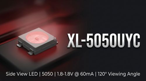
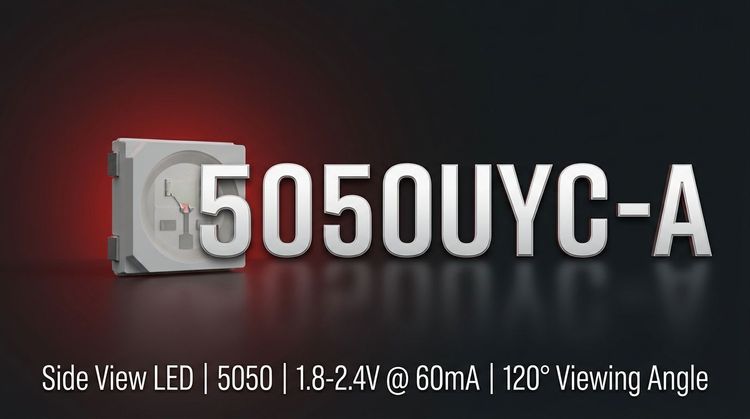
The XL-5050UYC-A from XINGLIGHT is a high-brightness yellow SMD LED integrated into a standard 5.0 x 5.0 x 1.6 mm package. 💡 It utilizes a water-clear colloid to maximize luminous intensity, making it suitable for applications requiring strong point-source illumination and wide-angle visibility. Designed to comply with RoHS directives and rated for MSL 3, this component supports modern automated SMT production lines and infrared reflow soldering processes.
🎯 Typical Applications
Based on its luminous intensity (1300–2000 mcd) and wide 120° viewing angle, the XL-5050UYC-A is optimized for:
- Commercial Indoor Lighting: General illumination and auxiliary task lighting.
- Signage & Advertising: LED modules for luminous characters and channel letters.
- Retail Display: Counter and jewelry cabinet lighting where color rendering and brightness consistency are critical.
- Decorative Illumination: Accent lighting solutions requiring compact form factors.
📊 Key Technical Specifications
The optical performance of the XL-5050UYC-A is categorized by specific binning codes to ensure uniformity in large-scale deployments. 👇 Designers should reference these bins when selecting replacements to maintain color consistency.
| Parameter | Symbol | Test Conditions | Value / Binning Codes |
|---|---|---|---|
| Luminous Intensity | Iv | IF = 60mA | 1300 ~ 2000 mcd (Bins: F3 to F6) |
| Dominant Wavelength | λd | IF = 60mA | 585 ~ 595 nm (Bins: HY03 to HY06) |
| Forward Voltage | VF | IF = 60mA | 1.8 ~ 2.4 V (Bins: N12-7 to N12-9) |
| Viewing Angle | 2Ø1/2 | IF = 60mA | 120° |
| Peak Wavelength | λp | IF = 60mA | 588 nm |
| Reverse Current | IR | VR = 5V | ≤ 5 μA |
⚠️ Absolute Maximum Ratings & Process Limits
Exceeding these parameters may result in permanent device failure. 🔒 The table below defines the stress limits for the XL-5050UYC-A under a Ta=25°C ambient temperature. Design margins must account for thermal derating when operating in enclosed fixtures.
| Parameter | Symbol | Max Value | Unit | Notes |
|---|---|---|---|---|
| Max Power Dissipation | PD | 200 | mW | |
| Max Continuous Forward Current | IF | 60 | mA | |
| Peak Forward Current | IFP | 120 | mA | Pulse ≤ 0.1ms, Duty ≤ 1/10 |
| Max Reverse Voltage | VR | 5 | V | |
| ESD Tolerance | ESD | 2000 | V | Human Body Model (HBM) |
| Operating Temperature | TOPR | -40 ~ +85 | °C | |
| Storage Temperature | TSTR | -40 ~ +85 | °C | |
| Soldering Temp/Time | TSOL | 260 | °C | ≤ 6 Seconds |
📦 Package, Dimensions & Assembly Notes
The device conforms to the EIA standard footprint for 5050 SMD components. The package dimensions are 5.0mm (L) x 5.0mm (W) x 1.6mm (H). 📐
- Soldering Compatibility: Suitable for both Lead and Lead-Free infrared reflow processes.
- Reflow Profile (Lead-Free): Peak temp max 255°C; time above 217°C should be 60–120 seconds.
- Moisture Sensitivity: Classified as MSL 3. Components must be baked according to J-STD-033 standards if the floor life is exceeded prior to reflow to prevent pop-corning or internal cracking.
🚀 Sourcing & Supply Considerations
When procuring the XL-5050UYC-A for mass production, specific attention must be paid to supply chain verification to avoid counterfeit or mixed-bin components.
- Binning Consistency: Verify that suppliers adhere to the strict "HY" (Wavelength) and "F" (Brightness) bin codes to ensure visual uniformity across advertising modules.
- ** authenticity Checks:** Cross-reference packaging markings and ESD ratings (2000V) upon receipt.
- Sample Evaluation: Request pre-production samples to validate the specific Forward Voltage (N12 series) bin for your driver circuit compatibility.
❓ FAQ
Q: What is the maximum current I can drive the XL-5050UYC-A with continuously?
A: The Absolute Maximum Rating for continuous forward current is 60 mA. While pulse currents can reach 120 mA, sustained operation above 60 mA will significantly degrade the LED lifespan and increase thermal failure risks.
Q: Which reflow soldering profile should be used for this LED?
A: The device supports infrared reflow. For lead-free processes (common in ROHS compliance), the peak temperature should not exceed 255°C, with duration above 217°C limited to 60–120 seconds.
Q: How do I ensure color consistency across multiple batches of XL-5050UYC-A?
A: You must specify the Dominant Wavelength bin code (e.g., HY03 to HY06) when ordering. The datasheet shows a 10nm range (585-595nm), so locking in a specific bin is critical for applications like jewelry lighting.
Q: What does the "N12-7" voltage bin mean?
A: The N12-7 code indicates the LED's Forward Voltage (VF) will fall between 1.8V and 2.0V at 60mA. Selecting the correct bin helps in designing constant current drivers with tighter voltage regulation windows.
Q: Is this component suitable for high-humidity environments?
A: Yes, it is rated for storage and operation in high humidity and has passed High Temperature/Humidity Storage tests (85°C / 90-95% RH). However, proper conformal coating on the PCB is recommended for the final application.
Q: What are the dimensions of the PCB footprint required?
A: The footprint is standard for 5050 packages. The land pattern should accommodate the 5.0 x 5.0 mm body size with appropriate pad extensions for solder fillets, adhering to EIA standards.