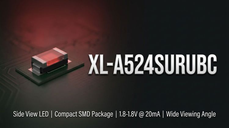
📌 Product Overview
The XL-A524SURUBC is an F5 round (5mm diameter) bi-color LED component featuring a common cathode configuration and a water-clear lens. 💡 It integrates high-brightness Red (640nm) and Blue (465nm) chips into a single package, allowing for dynamic status indication or RGB mixing in spatially constrained designs. This component is engineered to balance luminous intensity with energy efficiency, offering a direct drive solution compatible with standard low-voltage DC circuits. It targets applications requiring compact, durable light sources with stable optical performance.
🚀 Typical Applications
Based on its F5 footprint and bi-color luminous characteristics, the XL-A524SURUBC is suitable for the following scenarios:
- Backlight Modules: Indicator legends and LCD edge lighting for consumer appliances.
- Automotive Interiors: Dashboard illumination and cabin status signals where MSL 2 compliance is critical.
- Industrial Signal: Status towers and panel indicators requiring distinct Red/Blue states.
- Smart Home Devices: Feedback LEDs for IoT hubs and network switches.
- General Lighting: Decorative accent lighting and small-scale illumination tasks.
📈 Key Technical Specifications
The following optical and electrical parameters are measured under standard test conditions (Ta=25°C, IF=20mA), providing the baseline for design integration and binning selection.
| Parameter | Symbol | Red (Min/Typ) | Blue (Min/Typ) | Unit |
|---|---|---|---|---|
| Luminous Intensity | Iv | 400 / - | 900 / - | mcd |
| Dominant Wavelength | λd | 630 / - | 460 / - | nm |
| Forward Voltage | VF | 1.8 / - | 2.8 / - | V |
| Viewing Angle | 2θ1/2 | - / 30 | - / 30 | Degrees |
Note: Specific intensity rankings are available via Bin Codes A5–E1.
🔒 Absolute Maximum Ratings & Process Limits
Exceeding these ratings may cause permanent device failure or degradation of luminous performance. These limits are critical for maintaining reliability during surges or assembly.
| Parameter | Symbol | Red | Blue | Unit |
|---|---|---|---|---|
| Max Power Dissipation | PD | 50 | 70 | mW |
| Max Continuous Forward Current | IF | 20 | 20 | mA |
| Peak Forward Current | IFP | 80 | 80 | mA |
| Operating Temperature | TOPR | -20 to +85 | °C | |
| Storage Temperature | TSTR | -40 to +85 | °C |
⚠️ Caution: Soldering iron must not exceed 300°C for more than 3 seconds. Keep the soldering point >2.0mm from the colloid base to prevent thermal damage.
📦 Package, Dimensions & Assembly Notes
- Package Type: F5 Round (Diffused/Water Clear)
- Dimensions (L/W/H): 5.8mm x 5.0mm x 8.7mm (Body) with a 28mm lead pitch standard.
- Assembly Compatibility: Designed for wave soldering or manual insertion processes.
- Moisture Sensitivity: Rated at MSL Level 2. 🔒 To prevent popcorn cracking or moisture ingress, bake components before reflow if exposed to ambient conditions beyond the floor life.
- Packaging: EIA standard compliant packaging for automated feeder systems.
🤝 Sourcing & Supply Considerations
- Binning Verification: Verify the intensity and wavelength bin codes (A5–E1 / HB04–HR05) to ensure color consistency in your batch.
- Authenticity: Cross-reference the XL-A524SURUBC marking with XINGLIGHT factory datasheets to avoid off-spec components.
- Sample Evaluation: Request samples with specific voltage and brightness grades to validate driver circuit compatibility before volume ordering.
- Lead Time: Check stock availability for specific bin codes, as high-intensity grades may have longer lead times.
❓ FAQ
Q: What is the difference in voltage drop between the Red and Blue chips?
A: The Red chip has a typical forward voltage of 1.8V–2.4V, while the Blue chip requires a higher drive voltage of 2.8V–3.4V at 20mA. Your driver circuit must accommodate the higher Blue VF to regulate current correctly.
Q: Can this component be used in a reflow soldering process?
A: While the datasheet lists reflow parameters, the XL-A524SURUBC is primarily an F5 through-hole component. If reflowed, strict adherence to the MSL 2 preconditioning and a maximum temperature of 240°C for ≤6 seconds is required to protect the epoxy.
Q: How do I interpret the brightness bin codes (e.g., A6 vs. E1)?
A: The codes sort luminous intensity. "A6" ranges from 500–700 mcd (lower brightness), whereas "E1" ranges from 1500–1800 mcd (highest brightness). Selecting the correct bin ensures visual uniformity across your product line.
Q: What does "Common Cathode" mean for this model?
A: It means both the Red and Blue chips share a single negative connection (Cathode). The anodes are separate, allowing you to control Red, Blue, or the combined Purple state by switching the positive pins independently.
Q: How does the viewing angle affect my design?
A: With a 30-degree viewing angle, this LED focuses light in a narrow cone. It is ideal for indicator panels where light needs to be directed at the viewer rather than diffused broadly.