📌 Product Overview
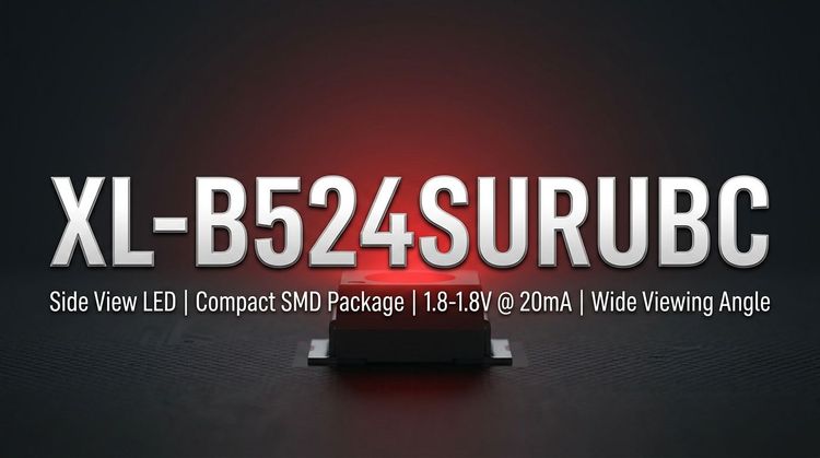
The XL-B524SURUBC is a standard F5 (5mm) bi-color LED designed by XINGLIGHT, integrating high-brightness Red and Blue emitters into a single diffused lens package. 🏗️ This component utilizes a common anode configuration, making it suitable for status indication and backlighting circuits requiring two-state color logic.
The device is engineered for robust performance in general lighting and signal applications, offering a diffused water-colored colloid for wide light dispersion. 🔧 Its design prioritizes low-voltage DC drive capabilities and long operational life, ensuring reliability in continuous use environments such as automotive interiors and home appliances.
💡 Typical Applications
Based on the F5 form factor and bi-color optical characteristics, the XL-B524SURUBC is optimized for the following specific use cases:
- Backlight Modules: Ideal for indicator panels and switch illumination where color state changes (e.g., Red for stop, Blue for active) are required.
- Automotive Interiors: Suitable for dashboard indicators and cabin lighting, provided the specific thermal environment stays within the -20°C to +85°C operating range.
- Signal Indication: Used in industrial control panels and consumer electronics for status reporting (Normal/Error states).
- Smart Home Devices: Integrated into IoT hubs or appliances to provide visual feedback in compact footprints.
⚡ Key Technical Specifications
The optical performance varies significantly between the Red and Blue chips. Designers must account for the differing forward voltages and luminous intensities when calculating current-limiting resistors.
| Parameter | Symbol | Red (Min/Max) | Blue (Min/Max) | Unit | Test Conditions |
|---|---|---|---|---|---|
| Luminous Intensity | Iv | 400 / 700 | 900 / 1800 | mcd | IF = 20mA |
| Dominant Wavelength | λd | 630 / 640 | 460 / 475 | nm | IF = 20mA |
| Forward Voltage | VF | 1.8 / 2.4 | 2.8 / 3.4 | V | IF = 20mA |
| Viewing Angle | 2Ø1/2 | - | 30 | deg | IF = 20mA |
⚠️ Note: The Blue chip provides higher luminous intensity (up to 1800mcd) compared to the Red chip, but requires a higher forward voltage drive.
🚨 Absolute Maximum Ratings & Process Limits
Exceeding these parameters may result in permanent device failure. These limits are critical for designing the driver circuit and ensuring thermal stability during assembly.
| Parameter | Symbol | Red | Blue | Unit |
|---|---|---|---|---|
| Max Power Dissipation | PD | 50 | 70 | mW |
| Max Continuous Forward Current | IF | 20 | 20 | mA |
| Peak Forward Current | IFP | 80 | 80 | mA |
| Operating Temperature | TOPR | -20 to +85 | -20 to +85 | °C |
| Storage Temperature | TSTR | -40 to +85 | -40 to +85 | °C |
Soldering Limits:
- Wave Soldering: Max 240°C for ≤6 seconds.
- Manual Welding: Max 300°C for ≤3 seconds.
- 🔒 Critical: The soldering point must be >2.0mm from the base of the colloid to prevent thermal damage to the epoxy package.
📦 Package, Dimensions & Assembly Notes
The XL-B524SURUBC features a standard radial leaded package with specific dimensional constraints for PCB integration.
- Dimensions: The overall package size is approximately 5.8mm (L) x 5.0mm (W) x 8.7mm (H), with a total length including leads of 28mm.
- Lens Type: Diffused (Water/Misty colloid) for wide-angle light distribution.
- MSL Rating: Moisture Sensitivity Level 2. Components must be mounted within 1 year of opening the sealed bag to prevent moisture-induced damage during reflow.
- Assembly: Standard EIA packaging compliance ensures compatibility with automatic insertion equipment.
🚀 Sourcing & Supply Considerations
When integrating the XL-B524SURUBC into a BOM, consider the following supply chain factors to mitigate production risks:
- Bin Code Management: The datasheet indicates specific binning codes for Brightness (A5-E1), Voltage (N12/N13), and Wavelength (HR/HB). Verify available bins with XINGLIGHT to ensure consistency across production lots.
- RoHS Compliance: The product is fully compliant with environmental protection standards, facilitating export to global markets.
- Sampling: Request samples specific to your target voltage and brightness bins to validate the visual appearance in your specific diffuser or housing design.
❓ FAQ
Q: What is the forward voltage difference between the Red and Blue chips?
A: The Red chip has a forward voltage range of 1.8V to 2.4V, while the Blue chip requires 2.8V to 3.4V. You must calculate separate current-limiting resistors for each color channel to ensure uniform brightness and prevent current overload.
Q: Can this LED be used in outdoor environments?
A: The datasheet specifies an operating temperature range of -20°C to +85°C. While suitable for indoor automotive interiors, it is not rated for extreme outdoor weather conditions unless adequately protected by an enclosure.
Q: What does "Common Anode" mean for this specific model?
A: "Common Anode" (indicated by "共阳" in the datasheet) means the positive (+) connection is shared between the Red and Blue diodes. You must connect the cathode (-) of each chip to the ground to activate the specific color.
Q: How strict is the soldering distance requirement?
A: The soldering point must be >2.0mm from the bottom of the epoxy body. Soldering closer than this risks thermal degradation of the colloid and internal wire bonds, especially during manual welding at 300°C.
Q: What is the typical lead time for the XL-B524SURUBC?
A: As a standard F5 component, lead times are generally stable, but availability depends on the specific Binning Code (Brightness/Wavelength) required. It is advisable to check stock for your specific bin codes before mass production.
Q: Is the XL-B524SURUBC compatible with automated assembly?
A: Yes, it adheres to EIA standard packaging specifications, making it compatible with automatic lead forming and insertion machines commonly used in EMS environments.