📌 Product Overview
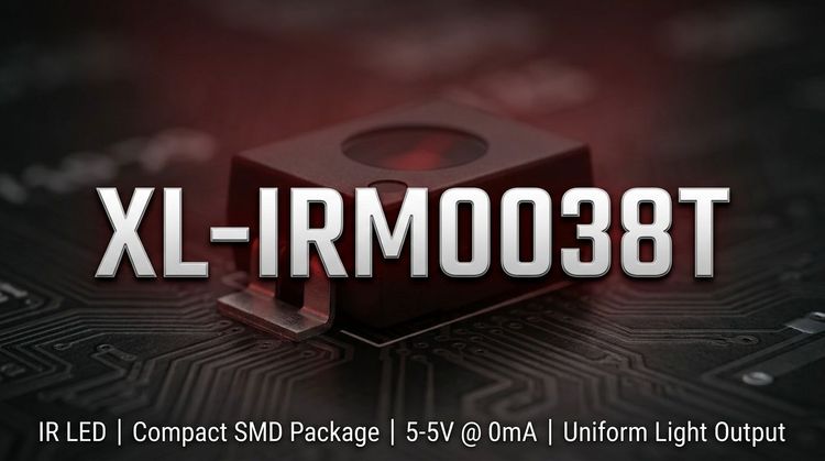
The XL-IRM0038T is a miniaturized infrared receiver module designed for 37.9 kHz remote control systems. It integrates a high-sensitivity PIN photodiode and a low-power preamplifier IC into a single epoxy package. 💡 This component is specifically engineered to provide stable signal detection in environments prone to electrical interference, making it suitable for compact consumer electronics and industrial applications where space and reliability are critical.
🛠 Typical Applications
- Consumer Appliances: Essential for user interfaces in air conditioners, fans, heaters, and humidifiers, providing reliable non-line-of-sight control.
- Multimedia Systems: Utilized in TVs, DVD players, and set-top boxes for decoding infrared commands from standard remote controls.
- Automotive & Industrial: 💡 Appropriate for in-car mobile DVD systems and industrial automation panels, where environmental noise resistance is required for consistent operation.
⚙ Key Technical Specifications
| Parameter | Symbol | Min. | Typ. | Max. | Unit | Test Conditions |
|---|---|---|---|---|---|---|
| Supply Voltage | VDD | 2.7 | - | 5.5 | V | Recommended Operating Range |
| Carrier Frequency | $f_o$ | - | 37.9 | - | kHz | Center Frequency |
| Working Current | $I_{CC}$ | 0.2 | 0.3 | 0.5 | mA | $V_{DD}=5V$ |
| Reception Distance | $L$ | - | 12 | - | m | $0^\circ$ Axis (Test specific) |
| Low Level Output | $V_{OL}$ | - | - | 250 | mV | $I_{sink}=2.0mA$ |
| High Level Output | $V_{OH}$ | 4.5 | - | 5.0 | V | $V_{CC}=5V$ |
Note: Reception distance drops to approx. 5–6m at $\pm 35^\circ$ angles.
⚠ Absolute Maximum Ratings & Process Limits
| Parameter | Symbol | Rating | Unit | Notes |
|---|---|---|---|---|
| Supply Voltage | $V_{DD}$ | 6.0 | V | |
| Operating Temp. | $T_{opr}$ | -20 ~ +85 | $^\circ$C | |
| Storage Temp. | $T_{stg}$ | -40 ~ +125 | $^\circ$C | |
| Wave Soldering | - | 260 | $^\circ$C | $\le 6s$ |
| Manual Welding | - | 300 | $^\circ$C | $\le 3s$ |
⚠️ Caution: Exceeding these limits may cause permanent damage to the module. Ensure strict adherence to soldering thermal profiles to prevent degradation of the internal die bond.
📦 Package, Dimensions & Assembly Notes
The device utilizes a semi-circular spherical epoxy resin plastic package (THT type).
- Dimensions: $5.5 \text{ (L)} \times 5.0 \text{ (W)} \times 4.9 \text{ (H)} \text{ mm}$.
- Pin Length: 22.5 mm.
- Shielding: Features internal and external dual shielding to resist electromagnetic interference (EMI).
🔒 Assembly: Standard wave soldering (260°C) is supported, but manual soldering should be limited to 300°C for under 3 seconds. The lead pitch is standard for PCB headers.
📦 Sourcing & Supply Considerations
- Certification Status: The XL-IRM0038T is fully REACH and RoHS compliant, ensuring suitability for export markets and environmental regulations.
- Packaging: Supplied in moisture-proof and anti-electrostatic foil bags to maintain component integrity prior to assembly.
- Grading Codes: Verify specific grading codes (V1/V2, L1/L3, I1/I2) on the label to match your precise voltage and distance requirements.
- Channel Verification: 💡 Procurement teams should verify authorized distribution channels to avoid counterfeits, as inconsistent internal shielding affects performance.
❓ FAQ
Q: What is the carrier frequency tolerance for the XL-IRM0038T?
A: The typical carrier frequency is 37.9 kHz. The Band Pass Filter (BPF) width is typically 6 kHz. This standard frequency makes it compatible with most general-purpose IR remote control protocols used in consumer electronics.
Q: Can this module be used directly with 3.3V microcontrollers?
A: Yes. 💡 The device has a wide operating voltage range of 2.7V to 5.5V. The output high level ($V_{OH}$) at 5V is 4.5V–5.0V, which is sufficient to be recognized as a logic high by 3.3V CMOS inputs, though verifying logic thresholds in the specific circuit design is recommended.
Q: How does the dual shielding design benefit the circuit?
A: The internal and external dual shielding design minimizes susceptibility to environmental electromagnetic interference (EMI), such as from fluorescent lights or switching power supplies. This ensures a lower bit error rate during signal reception.
Q: What are the thermal limits for assembly processes?
A: For wave soldering, the temperature should not exceed 260°C for more than 6 seconds. For manual welding, the limit is 300°C for 3 seconds. Adhering to these limits prevents damage to the epoxy encapsulation and the internal IC bond wires.
Q: Is the output active High or Low?
A: The output is active Low. When the valid infrared signal is detected, the output pin pulls low to a saturation voltage ($V_{OL}$) of max 250mV. When no signal is present, the output remains High.