📌 Product Overview
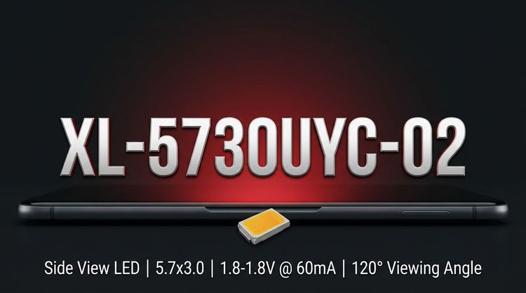
The XINGLIGHT XL-5730UYC-02 is a 5730 package Surface Mount Device (SMD) LED, characterized by high luminous intensity and a transparent yellow colloid. Designed for general illumination and display backlighting, this 0.2W component balances thermal performance with optical efficiency, offering a stable light source for compact commercial fixtures. Its primary design focus is on maintaining color consistency and reliable luminous flux within standard SMT assembly processes.
🚀 Typical Applications
Based on its 120-degree viewing angle and 585-595nm wavelength range, the XL-5730UYC-02 is suited for:
- Commercial Lighting: Downlights and office lighting tubes requiring uniform output.
- Signage & Display: Advertising lightboxes and channel letters where color consistency is critical.
- Backlighting: LCD modules and indicator strips needing a compact 5.7x3.0mm footprint.
- Decorative Lighting: Flexible light strips for ambient or accent lighting applications.
⚡ Key Technical Specifications
💡 The following table outlines the electro-optical performance under standard test conditions (Ta=25°C, IF=60mA), essential for BOM optimization and driver circuit design.
| Parameter | Symbol | Min. | Typ. | Max. | Unit | Condition |
|---|---|---|---|---|---|---|
| Luminous Intensity | IV | 400 | - | 700 | mcd | IF = 60mA |
| Dominant Wavelength | λd | 585 | 590 | 595 | nm | IF = 60mA |
| Forward Voltage | VF | 1.8 | - | 2.4 | V | IF = 60mA |
| Viewing Angle | 2θ1/2 | - | - | 120 | Deg | IF = 60mA |
👇 Note: Designers should account for the forward voltage variance (1.8V-2.4V) when configuring constant current drivers to ensure uniform brightness across large arrays.
🚨 Absolute Maximum Ratings & Process Limits
⚠️ Operating beyond these thresholds risks permanent optical degradation or catastrophic failure. These limits are critical for stress testing and protective circuit design.
| Parameter | Symbol | Max Value | Unit | Notes |
|---|---|---|---|---|
| Max Power Dissipation | PD | 200 | mW | @ Ta=25°C |
| Max Continuous Forward Current | IF | 60 | mA | DC operation |
| Peak Forward Current | IFP | 120 | mA | Pulse width ≤0.1ms |
| Max Reverse Voltage | VR | 5 | V | - |
| ESD Susceptibility | ESD | 2000 | V | Human Body Model (HBM) |
| Operating Temp. Range | TOPR | -40 ~ +85 | °C | - |
🔒 Thermal Warning: While the storage range extends to 85°C, derating the drive current is recommended in high-ambient temperature environments to prolong lifespan.
📦 Package, Dimensions & Assembly Notes
- Package Type: 5730 Surface Mount (SMD).
- Outline Dimensions: 5.7mm (L) x 3.0mm (W) x 0.8mm (H).
- Soldering Compatibility: Designed for Infrared Reflow Soldering. It is not suitable for wave soldering.
- Moisture Sensitivity: Classified as MSL 3.
- 📌 Requirement: Floor life at factory conditions (<30°C / 60% RH) must not exceed 168 hours. Baking is required before reflow if exposed longer.
- Lead-Free Process: Peak temperature limit is 260°C for ≤6 seconds.
🏭 Sourcing & Supply Considerations
- Binning Codes: XINGLIGHT provides specific binning for Brightness (E2-E6), Voltage (N12-7 to N12-9), and Wavelength (HY03-HY06). Verify these codes on the packaging label to ensure color uniformity in your batch.
- Authenticity: Cross-reference the packaging format (EIA standard) and printing clarity to avoid counterfeit components.
- Supply Chain: Standard EIA packaging simplifies pick-and-place processes, but verify lead times for specific voltage bins to prevent production bottlenecks.
❓ Frequently Asked Questions
Q: What does the MSL 3 rating mean for my assembly line?
A: MSL 3 (Moisture Sensitivity Level 3) means the components can be exposed to the factory air for a maximum of 168 hours (1 week) after the vacuum seal is broken. After this time, you must bake the LEDs at specific temperatures (usually 80-125°C for 24-48 hours) to remove internal moisture before reflow soldering to prevent "popcorning" or delamination.
Q: Can I drive this LED at 120mA continuously?
A: No. The 120mA rating is the Peak Forward Current (IFP) for pulses ≤0.1ms. The Max Continuous Forward Current (IF) is 60mA. Driving it continuously at 120mA will likely cause immediate thermal failure or drastically reduce the luminous lifespan.
Q: Why is the Forward Voltage (VF) range so wide (1.8V - 2.4V)?
A: This variance is typical for high-brightness LEDs due to manufacturing tolerances in the semiconductor die. In series circuits, this variance is negligible, but in parallel circuits, it can cause uneven current distribution (current hogging), leading to brightness inconsistency. Always use a series configuration or individual current regulation for each string.
Q: Is this component suitable for outdoor signage?
A: The LED itself has an operating range of -40°C to +85°C, making it suitable for the internal temperature ranges of outdoor signs. However, the IP rating of the final fixture is what determines protection against rain and dust. Ensure the housing provides adequate sealing and heat dissipation, as the LED's datasheet refers to the component performance, not the assembled fixture's environmental resistance.
Q: How do I interpret the Brightness Binning codes (E2-E6)?
A: These codes (e.g., E4: 500-550 mcd) allow you to purchase LEDs with tighter luminous intensity ranges. Selecting a single bin code ensures that all LEDs in a batch have matching brightness, which is crucial for applications like lightboxes where uneven lighting would be visually unacceptable.