📌 Product Overview
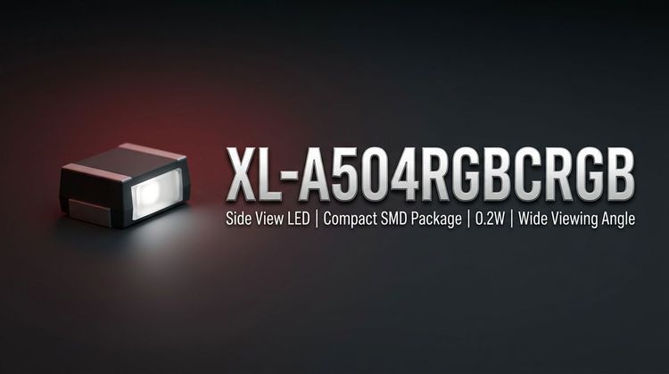
The XL-A504RGBCRGB is a Highlight RGB LED component manufactured by XINGLIGHT, characterized by a 5mm round appearance with a water-clear colloid. 💡 This component integrates discrete Red, Green, and Blue chips into a single package, allowing for a wide spectrum of color mixing in general lighting and indication applications. 🚀 The design prioritizes high energy efficiency with a standard operating life, suitable for environments requiring consistent luminous output.
🎯 Typical Applications
Based on its robust thermal range (-40°C to +85°C) and ESD protection (2000V), the XL-A504RGBCRGB is engineered for diverse integration scenarios:
- Backlight Modules: Providing uniform color mixing for LCD displays and indicator panels.
- Automotive Interiors: Utilized for dashboard illumination and ambient mood lighting.
- Smart Home Devices: Integrated into IoT hubs and appliances for status signaling.
- General Lighting: Suitable for decorative fixtures and compact RGB luminaires.
⚡ Key Technical Specifications
The electrical performance varies significantly by color, requiring careful current limiting resistor calculation for each chip.
| Parameter | Symbol | Red (R) | Green (G) | Blue (B) | Unit |
|---|---|---|---|---|---|
| Forward Voltage | VF | 1.8 - 2.4 | 2.8 - 3.4 | 2.8 - 3.4 | V |
| Forward Current | IF | 20 | 20 | 20 | mA |
| Luminous Intensity | IV | 700 - 1800 | 4000 - 6000 | 1000 - 1500 | mcd |
| Dominant Wavelength | λD | 620 - 630 | 515 - 530 | 460 - 470 | nm |
| Viewing Angle | 2θ1/2 | - | - | 35 | deg |
Note: Typical values measured at Ta=25°C. Green chips exhibit significantly higher luminous intensity compared to Red and Blue.
⚠️ Absolute Maximum Ratings & Process Limits
Exceeding these parameters risks irreversible damage to the LED junction. 🔒 Designers must ensure peak pulse currents remain within safe limits during multiplexing operations.
| Parameter | Symbol | Red | Green | Blue | Unit |
|---|---|---|---|---|---|
| Power Dissipation | Pd | 50 | 70 | 70 | mW |
| Peak Forward Current | IFP | 80 | 80 | 80 | mA |
| Reverse Voltage | VR | 5 | 5 | 5 | V |
| ESD Tolerance | ESD | - | 2000 | - | V |
| Operating Temp. | Topr | - | -40 ~ +85 | - | °C |
📦 Package, Dimensions & Assembly Notes
The component features a cylindrical appearance with dimensions of F5/5.85.08.7*28mm. ⚙️ Proper assembly requires strict adherence to soldering profiles to prevent胶体 (colloid) damage or degradation of the internal wire bonds.
- Wave Soldering: Max 240°C for ≤6 seconds.
- Manual Welding: Max 300°C for ≤3 seconds.
- Placement: The solder joint must be >2.0mm from the bottom of the colloid to ensure thermal isolation.
- MSL Level: 2 (Safe for factory floor exposure < 1 year at <30°C/60% RH).
🏭 Sourcing & Supply Considerations
When integrating the XL-A504RGBCRGB into BOMs, consider the following supply chain factors:
- Color Binning: Verify supplier availability for specific chromaticity codes (HG, HB, HR) to ensure color consistency across production batches.
- Packaging: The unit utilizes EIA standard packaging, ensuring compatibility with automated feeders for radial insertion if leads are pre-formed.
- Authenticity: Source from authorized channels to guarantee ROHS compliance and avoid moisture-sensitive components that may have been improperly stored.
❓ Frequently Asked Questions
Q: What is the forward voltage difference between the Red and Green/Blue chips?
A: The Red chip has a significantly lower forward voltage range (1.8V - 2.4V) compared to the Green and Blue chips (2.8V - 3.4V). 💡 Independent current control or appropriate resistors are necessary for each color to prevent imbalance.
Q: Can this LED be used in outdoor automotive applications?
A: While it has an operating temperature range of -40°C to +85°C, it is listed for "Automotive Interior" applications. 🚗 For exterior use, additional waterproofing measures may be required as the standard datasheet focuses on interior modules.
Q: What are the constraints for manual soldering of this component?
A: Manual welding must not exceed 300°C and should last no longer than 3 seconds. 🔥 Furthermore, the soldering point must be kept at least 2.0mm away from the base of the epoxy body to prevent thermal damage.
Q: How is brightness sorted for this specific model?
A: Brightness is graded using specific alphanumeric codes (e.g., A7, B8 for Green). 📈 Engineers should request specific bin codes based on the mcd requirements of their optical design to maintain uniformity.