📌 Product Overview
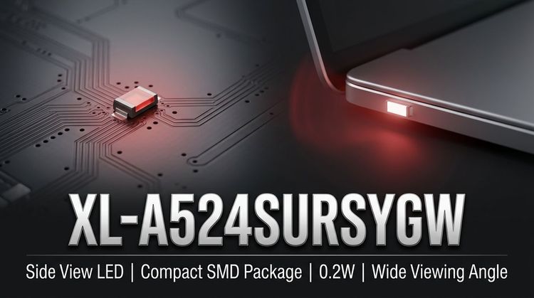
The XL-A524SURSYGW is a 5mm diameter bicolor indicator designed by XINGLIGHT, integrating high-brightness Red (640nm) and Yellow-Green (570nm) emitters into a single diffused package. 🛠️ It utilizes a standard F5 radial lead form factor with a water-clear, diffused colloid to ensure wide viewing angles and soft light distribution, suitable for status indication and backlighting panels.
Engineered for common cathode circuit designs, this component supports straightforward PCB integration while maintaining distinct color separation. The product is fully RoHS compliant and rated for Moisture Sensitivity Level 2 (MSL), ensuring reliability in standard assembly environments.
📌 Typical Applications
- Automotive Interior Indication: Dashboard illumination and control panel status lights due to stable luminosity across -20°C to +85°C.
- Backlight Modules: Diffused light source for LCD switches or small display panels.
- Signal Indication: Industrial equipment status lights (Power/OK) requiring clear Red/Yellow-Green differentiation.
- Smart Home Devices: User interface feedback LEDs for appliances or IoT hubs.
- General Lighting: Low-power pilot lights in consumer electronics.
🛠️ Key Technical Specifications
| Parameter | Symbol | Red (Min / Typ / Max) | Yellow-Green (Min / Typ / Max) | Unit | Test Conditions |
|---|---|---|---|---|---|
| Luminous Intensity | $I_V$ | 400 / - / 700 | 50 / - / 300 | mcd | $I_F = 20\text{mA}$ |
| Dominant Wavelength | $\lambda_d$ | 630 / - / 640 | 565 / - / 575 | nm | $I_F = 20\text{mA}$ |
| Forward Voltage | $V_F$ | 1.8 / - / 2.4 | 1.8 / - / 2.6 | V | $I_F = 20\text{mA}$ |
| Viewing Angle | $2\theta_{1/2}$ | - / 30 / - | - / 30 / - | Degrees | $I_F = 20\text{mA}$ |
| Reverse Current | $I_R$ | - / - / $\le 10$ | - / - / $\le 10$ | $\mu\text{A}$ | $V_R = 5\text{V}$ |
💡 Design Note: The component offers tight voltage bins (N12-7 to N13-1) and wavelength grading (HR/HYG codes), facilitating color consistency in mass production.
⚠️ Absolute Maximum Ratings & Process Limits
| Parameter | Symbol | Red | Yellow-Green | Unit | Notes |
|---|---|---|---|---|---|
| Max Power Dissipation | $P_D$ | 50 | 70 | mW | |
| Max Continuous Forward Current | $I_F$ | 20 | 20 | mA | |
| Peak Forward Current | $I_{FP}$ | 80 | 80 | mA | Pulse width $\le 10\text{ms}$, Duty $\le 1/10$ |
| Operating Temperature | $T_{OPR}$ | -20 ~ +85 | -20 ~ +85 | °C | |
| Storage Temperature | $T_{STG}$ | -40 ~ +85 | -40 ~ +85 | °C | |
| Soldering Temp | $T_{SOL}$ | Max 300°C (Manual, 3s) | Max 240°C (Wave, 6s) | °C | Distance from body: $\ge 2.0\text{mm}$ |
🚫 Critical Limit: Derating is required above 25°C ambient temperature to prevent thermal overload.
📏 Package, Dimensions & Assembly Notes
- Package Type: F5 Round Radial (Diffused Lens)
- Dimensions: The overall length is approximately 28mm, with a bulb diameter of 5.0mm. The spacing between leads follows standard EIA compliant packaging norms.
- Assembly Guidance: Ensure the solder joint is maintained at least 2.0mm from the base of the epoxy body to prevent thermal damage during wave soldering (max 240°C) or manual welding (max 300°C).
- Moisture Sensitivity: MSL Level 2. Components must be baked if exposed to ambient moisture for more than 1 year before reflow.
📦 Sourcing & Supply Considerations
- Supply Chain: Verify authentic XINGLIGHT distribution channels to avoid mixed batches.
- Binning Codes: Specify Brightness (A1-A6) and Voltage (N12-7 to N13-1) codes when placing orders to ensure uniformity in forward voltage and light output.
- Quality Compliance: The device meets ROHS environmental standards and has undergone 1000-hour reliability testing (High Temp/Humidity) with 0 failures.
- Cross-Reference: Check footprint compatibility (5mm F5) if substituting for other common cathode bicolor LEDs.
❓ FAQ
Q: Can the XL-A524SURSYGW be used in automotive exterior lighting?
A: No, this component is rated for Automotive Interior applications and general indication. It lacks the specific sealing and intensity requirements for exterior exposure.
Q: What is the difference between "Red" and "Yellow-Green" power dissipation limits?
A: The Red chip has a max dissipation of 50mW, while the Yellow-Green chip is rated for 70mW. Designers must calculate current limiting resistors for each channel separately to avoid exceeding these individual limits.
Q: What does "Common Cathode" mean for my circuit design?
A: It means the negative legs (cathodes) of both the Red and Yellow-Green LEDs are internally connected together, likely sharing one lead. The two positive leads (Anodes) remain separate to control colors individually.
Q: How should I handle storage to prevent moisture damage?
A: Store in a dry environment. Although MSL is Level 2 (allowing up to 1 year floor life at <30°C/60% RH), always verify the baking requirements if the packaging has been opened for extended periods prior to soldering.
Q: Are there specific soldering profile recommendations?
A: Yes. Keep soldering points 2.0mm away from the colloid base. Do not exceed 300°C for more than 3 seconds during manual soldering.