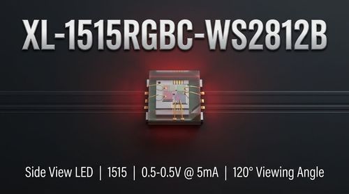
📌 Product Overview
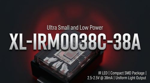
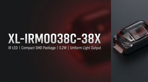
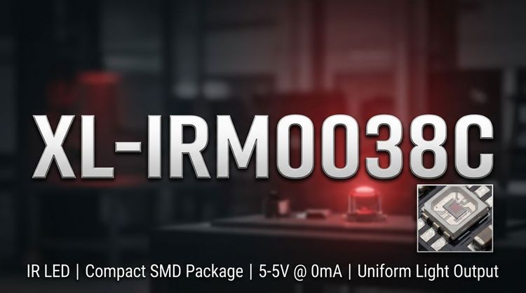
The XL-IRM0038C is a 3-pin infrared receiver designed to convert optical signals into TTL/CMOS compatible electrical outputs. 💡 It integrates a high-speed PIN photodiode and a high-gain preamplifier IC within a single epoxy package. This device focuses on minimizing space consumption while maximizing immunity against electromagnetic interference (EMI), thanks to its dual shielding design. It is ideally suited for compact infrared remote control systems in consumer electronics and industrial automation where reliability and signal integrity are critical.
🎯 Typical Applications
- Consumer Appliances: Air conditioners, fans, heaters, and humidifiers.
- Multimedia Systems: Televisions, DVD players, set-top boxes, and vehicle-mounted mobile DVD units.
- Industrial & Office: Instrumentation, industrial automation controls, and office machinery.
- Automotive & Lighting: Automotive electronics and intelligent lighting systems.
- Peripherals: Computer accessories and induction sanitary ware requiring contactless control.
⚙️ Key Technical Specifications
| Parameter | Symbol | Test Condition | Min | Typ | Max | Unit |
|---|---|---|---|---|---|---|
| Supply Voltage | VDD | Recommended | 2.7 | - | 5.5 | V |
| Carrier Frequency | f₀ | - | - | 37.9 | - | kHz |
| BPF Width | fBW | - | - | 6 | - | kHz |
| Low Level Output | VOL | Isink = 2.0mA | - | - | 250 | mV |
| High Level Output | VOH | VCC = 5V | 4.5 | - | 5.0 | V |
| Reception Distance | L | 0° | 15 | 20 | - | m |
| Working Current | ICC | VDD = 5V | 0.3 | 0.4 | 0.5 | mA |
⚠️ Absolute Maximum Ratings & Process Limits
👇 Exceeding these ratings may cause permanent damage to the device. Design margins must account for these limits.
| Parameter | Symbol | Rating | Unit |
|---|---|---|---|
| Supply Voltage | VDD | 6.0 | V |
| Operating Temp. | Topr | -20 to +85 | °C |
| Storage Temp. | Tstg | -40 to +125 | °C |
| Wave Soldering | Tsol | 240°C, ≤6s | - |
| Manual Soldering | Tsol | 300°C, ≤3s | - |
📦 Package, Dimensions & Assembly Notes
The device utilizes a small volume epoxy resin plastic sealing patch (SMD) design. The semi-circular spherical top enhances light reception, while the internal and external shielding reduces noise susceptibility.
- Dimensions: 4.5mm (L) x 4.0mm (W) x 2.3mm (H)
- Pin Length: 3.1mm
- Assembly: Compatible with standard wave soldering (max 240°C for 6 seconds) and manual soldering. 👇 Ensure PCB layout tolerances accommodate the 4.5mm length to prevent mechanical stress on the module.
🚀 Sourcing & Supply Considerations
The XL-IRM0038C is fully compliant with REACH and ROHS standards, ensuring adherence to environmental regulations. XINGLIGHT maintains consistency in gain and sensitivity, which is vital for mass production yield. When qualifying this component, verify the specific carrier frequency alignment (37.9kHz) with your existing remote control emitters.
❓ FAQ
Q: What is the standard carrier frequency for the XL-IRM0038C?
A: The typical carrier frequency (f₀) is 37.9 kHz with a Band Pass Filter (BPF) width of 6 kHz.
Q: Is the output compatible with standard 5V logic?
A: Yes, the High Level Output (VOH) ranges from 4.5V to 5.0V at VCC=5V, making it fully compatible with TTL and CMOS logic. The output is active low.
Q: What are the constraints for wave soldering this component?
A: The maximum temperature for wave soldering is 240°C for a duration not exceeding 6 seconds. Manual welding allows 300°C for 3 seconds.
Q: Does this module require an external shield?
A: No, the XL-IRM0038C features a built-in dual shielding design (internal and external) to withstand environmental interference, eliminating the need for additional PCB shielding in most standard environments.
Q: What is the operating voltage range for this IR receiver?
A: The recommended working voltage range is wide, from 2.7V to 5.5V, making it suitable for both 3.3V and 5V systems.