📌 Product Overview
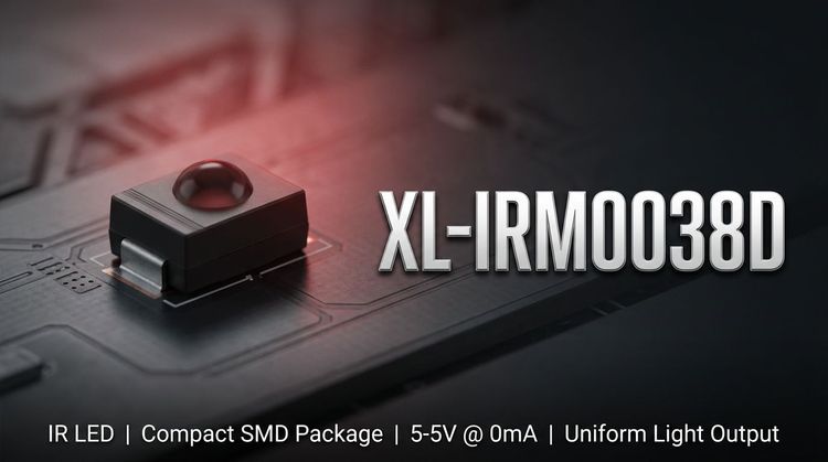
💡 The XL-IRM0038D is a high-sensitivity infrared receiver head designed for integration into remote control systems. It combines a PIN photodiode and a high-gain preamplifier IC within a compact epoxy resin package. The device is engineered to detect infrared signals at a carrier frequency of 37.9 kHz.
👇 This component is specifically optimized for applications requiring low power consumption and high immunity to environmental interference. Its design features dual-shielding (internal and external) to maintain signal stability against electromagnetic noise. It is suitable for surface-mount assembly processes requiring reliable performance in compact circuit designs.
🚀 Typical Applications
- Consumer Electronics: Air conditioners, fans, heaters, and humidifiers.
- Multimedia Devices: Televisions, DVD players, set-top boxes, and vehicle-mounted mobile DVD systems.
- Computer Peripherals: Interface devices for PCs and induction sanitaryware.
- Industrial Automation: Instrumentation and industrial control panels.
- Specialized Electronics: Remote control toys, photography equipment, financial terminals, and automotive lighting systems.
📊 Key Technical Specifications
💡 The following table outlines the standard electrical and optical characteristics at $T_a = 25^\circ C$ under specific test conditions.
| Parameter | Symbol | Min. | Typ. | Max. | Unit | Test Conditions |
|---|---|---|---|---|---|---|
| Supply Voltage | $V_{DD}$ | 2.7 | - | 5.5 | V | Recommended Range |
| Carrier Frequency | $f_o$ | - | 37.9 | - | kHz | - |
| Working Current | $I_{CC}$ | 0.3 | 0.4 | 0.5 | mA | $V_{DD}=5V$ |
| Reception Distance | $L$ (0°) | 10 | 15 | - | m | Standard Test |
| Reception Distance | $L$ ($\pm35^\circ$) | 5 | 6 | - | m | Side Angle |
| Low Level Output | $V_{OL}$ | - | - | 250 | mV | $I_{sink}=2.0mA$ |
| High Level Output | $V_{OH}$ | 4.5 | - | 5.0 | V | $V_{CC}=5V$ |
| BPF Width | $f_{BW}$ | - | 6 | - | kHz | - |
📈 Note: The output is compatible with TTL and CMOS logic levels and is active low.
🔒 Absolute Maximum Ratings & Process Limits
⚠️ Exceeding these limits may cause permanent damage to the device. Stress beyond these ratings for extended periods affects reliability.
| Parameter | Symbol | Rating | Unit | Notes |
|---|---|---|---|---|
| Supply Voltage | $V_{DD}$ | 6.0 | V | Do not exceed |
| Operating Temp. | $T_{opr}$ | -20 to +85 | $^\circ C$ | Ambient range |
| Storage Temp. | $T_{stg}$ | -40 to +125 | $^\circ C$ | Non-operating |
| Wave Soldering | $T_{sol}$ | 240 | $^\circ C$ | $\le 6s$ duration |
| Manual Welding | $T_{sol}$ | 300 | $^\circ C$ | $\le 3s$ duration |
💡 Pulse Width Constraints:
- Min Burst Width: 350 $\mu s$
- Min Burst Gap: 450 $\mu s$
📦 Package, Dimensions & Assembly Notes
The XL-IRM0038D utilizes a semi-circular spherical epoxy molding with a 1.27mm small foot pitch.
Dimensions (Length $\times$ Width $\times$ Height $\times$ Pin Length):
- 4.5mm $\times$ 4.0mm $\times$ 2.3mm $\times$ 2.2mm
Assembly Guidelines:
- The compact footprint facilitates high-density PCB layout.
- Ensure the carrier frequency of the transmitter matches the 37.9 kHz center frequency for optimal reception.
- The metal case acts as an EMI shield; ensure proper grounding during the PCB design to maximize the anti-interference capability.
- Avoid direct exposure of the receiver window to strong sunlight or high-frequency fluorescent lighting to prevent signal saturation.
🛒 Sourcing & Supply Considerations
- Certification Compliance: The module is REACH and ROHS certified, ensuring compliance with environmental standards for global distribution.
- BOM Integration: Designed as a drop-in component for standard infrared remote control circuits.
- Supply Verification: Procurement teams should verify the shielding construction to ensure consistency in high-interference environments.
- Sample Evaluation: Testing under specific lighting conditions (200 ± 50 Lux) is recommended to validate immunity against local light noise sources.
❓ FAQ
Q: What is the typical supply voltage range for the XL-IRM0038D?
A: The recommended operating voltage range is 2.7V to 5.5V, with an absolute maximum limit of 6.0V.
Q: How does the module handle signal interference?
A: It features an internal and external dual-shielding design and uses a Band Pass Filter (BPF) with a width of 6kHz to withstand environmental interference.
Q: What are the soldering temperature limits for this component?
A: For wave soldering, the limit is 240°C for $\le 6$ seconds. For manual welding, the limit is 300°C for $\le 3$ seconds.
Q: Is the output signal TTL or CMOS compatible?
A: The output matches both TTL and CMOS logic levels, operating with an active low configuration.
Q: What is the maximum reception distance?
A: Under standard test conditions ($V_{DD}=5V$), the typical reception distance is 15 meters at 0 degrees and 6 meters at $\pm 35$ degrees.
Q: Can this component be used in automotive applications?
A: While designed for automotive electronics, ensure the operating temperature range (-20°C to +85°C) meets the specific environmental requirements of the installation location.