📌 Product Overview
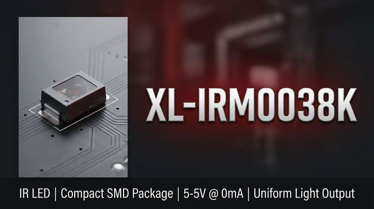
The XL-IRM0038K is a standard infrared receiver module designed for remote control systems, integrating a PIN photodiode and a preamplifier IC into a single epoxy resin package. This component is specifically engineered for consumer electronics and industrial automation, utilizing a 37.9 kHz carrier frequency to process infrared signals from standard remote transmitters. Key design focus areas include its semi-circular spherical packaging, which accommodates a wide-angle reception lens, and an internal shield structure that mitigates electrical interference. 💡
⚙️ Typical Applications
This device is widely utilized in scenarios requiring reliable, non-contact control across multiple sectors:
- Consumer Appliances: Air conditioners, fans, heaters, and humidifiers.
- Multimedia Systems: Televisions, DVD players, set-top boxes, and车载 DVD units.
- Industrial & Computing: Instrumentation, industrial automation controls, and computer peripherals.
- Automotive & Lighting: Automotive electronics and intelligent lighting systems. 👇
📊 Key Technical Specifications
The electrical performance is optimized for low power consumption and compatibility with standard logic levels.
| Parameter | Symbol | Test Conditions | Min | Typ | Max | Unit |
|---|---|---|---|---|---|---|
| Supply Voltage | VDD | - | 2.7 | - | 5.5 | V |
| Carrier Frequency | f₀ | - | - | 37.9 | - | kHz |
| Working Current | ICC | VDD=5V | 0.3 | 0.4 | 0.5 | mA |
| ** Reception Distance** | L | 0°, Test input | 15 | 20 | - | m |
| High Level Output | VOH | VCC=5V | 4.5 | - | 5.0 | V |
| Low Level Output | VOL | Isink=2.0mA | - | - | 250 | mV |
💡 The low-level active output ensures direct interfacing with TTL and CMOS microcontrollers without additional signal conditioning.
🚨 Absolute Maximum Ratings & Process Limits
Exceeding these values may cause permanent damage to the device. Design margins must account for these limits during power regulation and PCB assembly.
| Parameter | Symbol | Ratings | Unit |
|---|---|---|---|
| Supply Voltage | VDD | 6.0 | V |
| Operating Temp | Topr | -20 to +85 | °C |
| Storage Temp | Tstg | -40 to +125 | °C |
| Wave Soldering | Tsol | 240, ≤6s | °C |
| Manual Welding | Tsol | 300, 3s | °C |
🔒 The internal shielding structure provides immunity against environmental interference, but soldering duration must be strictly controlled to prevent epoxy degradation.
📦 Package, Dimensions & Assembly Notes
The module features a large volume, semi-circular spherical epoxy encapsulation designed for improved light reception and physical durability.
- Dimensions: 6.8mm (L) × 6.0mm (W) × 5.5mm (H).
- Pin Length: 21mm (suitable for through-hole PCB mounting).
- Packaging Type: Epoxy resin plastic encapsulation.
- Shielding: Dual shielding (internal and external) for anti-interference.
🚨 Ensure adequate spacing on the PCB layout to accommodate the 21mm pin length and prevent mechanical stress on the epoxy body during assembly.
📈 Sourcing & Supply Considerations
For engineers integrating the XL-IRM0038K into BOMs, verify the carrier frequency compatibility with existing remote control emitters (standard 37.9 kHz). ✨
- Certifications: Confirm REACH and ROHS compliance for environmental standards in your target market.
- Quality Control: Request inspection data for the dual-shielding integrity to ensure consistent EMI performance.
- Procurement: Verify stock authenticity and lead times for high-volume production runs. 👇
❓ FAQ
Q: What is the carrier frequency tolerance for the XL-IRM0038K?
A: The typical carrier frequency is centered at 37.9 kHz with a Band Pass Filter (BPF) width of 6 kHz.
Q: Can this receiver be used in outdoor sunlight applications?
A: While it features anti-interference design, direct sunlight can saturate the PIN diode. It is primarily designed for indoor use; specific testing is recommended for high-ambient-light environments.
Q: What is the supply voltage range for stable operation?
A: The device supports a wide operating voltage range from 2.7V to 5.5V, making it compatible with both 3.3V and 5V logic systems.
Q: How does the module handle environmental electrical noise?
A: It utilizes a dual shielding design (internal and external) and specific BPF characteristics to withstand environmental interference, ensuring reliable TTL/CMOS output.
Q: What are the soldering limits to prevent damage?
A: For wave soldering, limits are 240°C for ≤6 seconds. For manual welding, do not exceed 300°C for 3 seconds.
Q: Is the output compatible with standard microcontrollers?
A: Yes, the output is designed to be TTL and CMOS compatible and is active low, allowing direct connection to most MCU GPIO pins.