📌 Product Overview
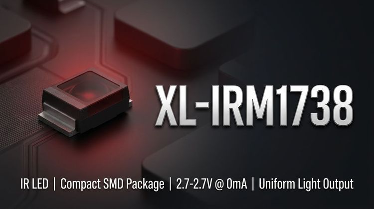
💡 The XL-IRM1738 from XINGLIGHT is a high-sensitivity infrared receiver module designed for reliable signal demodulation in remote control systems. This component integrates a PIN photodiode and a high-gain preamplifier IC into a single, compact epoxy package. It is engineered to support standard 37.9 kHz carrier frequencies commonly used in consumer electronics.
The module features a "nose bridge" epoxy encapsulation with dual internal and external shielding, ensuring resistance against environmental electrical interference. It is designed for voltage-flexible designs, operating within a range of 2.7V to 5.5V. Target applications include household appliances, audio-visual equipment, and industrial control interfaces. Key design considerations include its low power consumption and wide reception angle, which simplify PCB layout challenges in compact chassis.
🛠️ Typical Applications
🚀 This component is versatile across various sectors requiring infrared data reception. Based on its technical specifications and environmental ratings, the XL-IRM1738 is ideal for the following scenarios:
- Consumer Electronics: Televisions, set-top boxes, and DVD players where reliable remote command execution is critical.
- Home Appliances: Integration into air conditioners, fans, and heaters for user interface control.
- Automotive Systems: In-car entertainment and mobile DVD systems, benefiting from the wide operating temperature range.
- Industrial & Financial: Instrumentation panels and automated teller machines (ATMs) requiring precise signal decoding.
- Smart Lighting: Control modules for LED lighting systems and automated sanitary ware.
📊 Key Technical Specifications
| Parameter | Symbol | Min. | Typ. | Max. | Unit | Test Conditions |
|---|---|---|---|---|---|---|
| Supply Voltage | VDD | 2.7 | - | 5.5 | V | Recommended Operating |
| Carrier Frequency | f₀ | - | 37.9 | - | kHz | - |
| BPF Width | fBW | - | 6 | - | kHz | - |
| Working Current | ICC | 0.3 | 0.4 | 0.5 | mA | VDD = 5V |
| Reception Distance | L (0°) | 6 | 8 | - | m | Standard Test* |
| Reception Distance | L (±35°) | 5 | 6 | - | m | Standard Test* |
| Low Level Output | VOL | - | - | 250 | mV | Isink = 2.0mA |
| High Level Output | VOH | 4.5 | - | 5.0 | V | VCC = 5V |
*Test Condition: Emitter CH3018-12U, no direct sunlight, 40W fluorescent light interference at 200±50Lux.
⚠️ Absolute Maximum Ratings & Process Limits
🔒 Stress beyond these limits may cause permanent damage to the device. Designers must ensure these values are not exceeded during transient conditions or assembly.
| Parameter | Symbol | Rating | Unit | Notes |
|---|---|---|---|---|
| Supply Voltage | VDD | 6.0 | V | Continuous operation |
| Operating Temp. | Topr | -20 ~ +85 | °C | Ambient temperature |
| Storage Temp. | Tstg | -40 ~ +125 | °C | Non-operating |
| Soldering (Wave) | Tsol | 240 | °C | ≤ 6 seconds duration |
| Soldering (Manual) | Tsol | 300 | °C | ≤ 3 seconds duration |
| Min Pulse Width | Tburst | 350 | - | µs |
| Min Interval Time | Tburst gap | 450 | - | µs |
⚠️ Note: The device uses active-low output logic. Ensure the microcontroller pull-up resistors are compatible with the VOL specifications to prevent logic errors.
📦 Package, Dimensions & Assembly Notes
✨ The XL-IRM1738 utilizes a "Large Volume Epoxy Plastic Nose Bridge Packaging," which shields the detector from ambient light while focusing the infrared signal. This physical design contributes to the module's wide reception angle.
Dimensions (Length × Width × Height × Pin Length):
- 6.7 mm × 5.3 mm × 4.5 mm × 22 mm
PCB Assembly Considerations:
- Footprint: Designers should accommodate the 22mm pin length for through-hole insertion or lead forming.
- Shielding: The metalized inner and outer shield acts as a Faraday cage; ensure the ground connection on the PCB is robust to maintain EMI immunity.
- Placement: Keep the receiver window clear of obstructions (e.g., chassis bezels) to maintain the 0° to 35° reception efficiency.
📈 Sourcing & Supply Considerations
💡 When integrating the XL-IRM1738 into a Bill of Materials (BOM), consider the following supply chain and verification factors:
- Compliance: The module is REACH and ROHS certified, ensuring suitability for export to EU and other regulated markets.
- Consistency: Request "binned" data on reception distance if the application is sensitive to range variance.
- Samples: Always verify the carrier frequency tolerance (37.9 kHz) against the specific emitter IC in your design to prevent signal drop-out.
- Authentication: Source from authorized distributors to avoid counterfeit parts lacking the specified dual shielding or internal IC quality.
❓ Frequently Asked Questions
Q: What is the carrier frequency tolerance of the XL-IRM1738?
A: The typical center frequency is 37.9 kHz with a bandwidth (BPF width) of 6 kHz. This allows for slight deviations in the transmitter's carrier frequency without significant signal loss.
Q: Can this receiver be used in outdoor applications?
A: While the operating temperature range supports outdoor conditions (-20°C to +85°C), direct sunlight exposure is not recommended. Intense IR radiation from the sun can saturate the PIN diode, causing temporary "blindness" or signal disruption.
Q: What does "active low" output mean for this module?
A: The output pin remains at a logic High level (VDD) when no signal is received. When a valid 37.9 kHz signal is detected, the pin pulls down to a logic Low level (VOL < 250mV). This is designed to drive TTL or CMOS inputs directly.
Q: How does the "dual shielding" feature benefit the design?
A: The dual shielding (internal and external) significantly reduces electromagnetic interference (EMI) from the environment and the device's own circuitry. This improves reliability in electrically noisy environments like those with switching power supplies or motors.
Q: What is the minimum gap required between transmission codes?
A: The datasheet specifies a minimum interval time (Tburst gap) of 450 µs. Your transmission protocol must ensure gaps between data bursts meet or exceed this duration for the receiver to reset correctly.
Q: Is the XL-IRM1738 compatible with 3.3V microcontrollers?
A: Yes. The supply voltage range is 2.7V to 5.5V. However, while the input logic is compatible, verify that the High Level Output (VOH) meets the logic high threshold (VIH) of your specific microcontroller when operating at the lower end of the voltage range.