📌 Product Overview
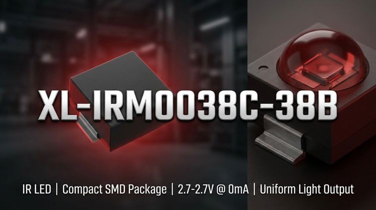
The XL-IRM0038C-38B is a miniaturized infrared receiver module integrating a high-sensitivity PIN photodiode and a low-power preamplifier IC into a single epoxy resin package. 💡 Its design utilizes an inner and outer dual-shielding structure to mitigate environmental electromagnetic interference, ensuring stable signal processing in crowded PCB environments.
Targeting SMT assembly lines, this component is engineered for 3.5mm low-profile applications in home appliances and multimedia devices. The focus for design engineers lies in its wide operating voltage range (2.7V–5.5V) and compatibility with standard TTL/CMOS logic levels, facilitating drop-in integration into microcontroller-based circuits.
🔎 Typical Applications
Based on the 37.9kHz carrier frequency and reception distance characteristics, the XL-IRM0038C-38B is optimized for the following scenarios:
- Consumer Appliances: Air conditioners, fans, heaters, and humidifiers requiring reliable handheld control.
- Multimedia Systems: TVs, DVD players, set-top boxes, and vehicle-mounted mobile entertainment units.
- Industrial & Peripheral: Instrumentation panels, industrial automation controllers, and computer peripheral inputs.
- Specialty Electronics: Induction sanitary ware, remote-controlled toys, and automotive electronics.
📊 Key Technical Specifications
Under standard test conditions (Ta=25°C, VDD=5V), the electrical performance is defined below.
| Parameter | Symbol | Min. | Typ. | Max. | Unit | Condition |
|---|---|---|---|---|---|---|
| Supply Voltage | VDD | 2.7 | - | 5.5 | V | Operating Range |
| Carrier Frequency | f0 | - | 37.9 | - | kHz | Center Frequency |
| BPF Width | fBW | - | 6 | - | kHz | Bandwidth |
| Working Current | ICC | 0.3 | 0.4 | 0.5 | mA | VDD=5V |
| Reception Distance | L (0°) | 10 | 15 | - | m | Standard Test |
| Low Level Output | Vol | - | - | 250 | mV | Isink=2.0mA |
| High Level Output | Voh | 4.5 | - | 5.0 | V | VCC=5V |
⚠️ Note: Reception distance drops to approx. 5m–6m when the transmission angle exceeds ±35°.
⚠️ Absolute Maximum Ratings & Process Limits
Exceeding these ratings may cause permanent damage to the device. Stress beyond these limits for extended periods affects reliability.
| Parameter | Symbol | Rating | Unit | Notes |
|---|---|---|---|---|
| Supply Voltage | VDD | 6.0 | V | Maximum input tolerance |
| Operating Temp | Topr | -20 to +85 | °C | Ambient working range |
| Storage Temp | Tstg | -40 to +125 | °C | Non-operating environment |
| Wave Soldering | Tsol | 260 | °C | Max 6 seconds duration |
| Manual Welding | Tsol | 300 | °C | Max 3 seconds duration |
💡 Engineering teams must strictly control soldering profiles to prevent degradation of the internal epoxy shielding and optical performance.
📦 Package, Dimensions & Assembly Notes
The device utilizes a semi-circular spherical black epoxy encapsulation designed for infrared transmission and visible light cut-off.
- Package Type: SMD Patch (Surface Mount Device)
- Dimensions (LxWxH): 5.0mm × 5.0mm × 3.5mm
- Pin Length: 3.1mm (Pitch dependent on PCB layout)
- Shielding: Dual-shielding design (internal & external) for EMI immunity.
👇 Assembly Note: The datasheet specifies compatibility with both wave soldering (≤260°C) and manual welding processes. Ensure the placement nozzle does not crack the epoxy dome during pick-and-place operations to maintain optical integrity.
🚀 Sourcing & Supply Considerations
- Environmental Compliance: Verified REACH and ROHS certification, suitable for global export markets requiring eco-friendly assemblies.
- Supply Chain: Risk mitigation involves checking lead times for the specific "semi-circular" epoxy variant versus standard flat-top receivers.
- Quality Control: Request binning data on the carrier frequency (37.9kHz) to ensure consistency with your remote control emitter IC.
❓ FAQ
Q: What is the carrier frequency tolerance for this specific IR receiver module?
A: The XL-IRM0038C-38B is tuned to a typical center frequency (f0) of 37.9 kHz with a Band Pass Filter (BPF) width of 6 kHz. This standard frequency is suitable for most general-purpose remote control protocols.
Q: Can this component be used in automotive electronics exposed to higher temperatures?
A: While suitable for automotive electronics (e.g., car DVD), the operating ambient temperature range is rated from -20°C to +85°C. For under-hood applications or extreme environments, additional thermal derating or a wider-spec component may be required.
Q: How does the dual-shielding design benefit the PCB layout?
A: The internal and external shielding minimizes interference from ambient light and nearby electrical noise on the board. This allows for more flexible placement closer to noise-generating components (like power supplies) without signal degradation.
Q: What are the critical soldering limits for mass production assembly?
A: For wave soldering, the temperature must not exceed 260°C for more than 6 seconds. For manual repair or touch-up soldering, the limit is 300°C for a maximum of 3 seconds to prevent damage to the internal die.
Q: Is the output compatible with 3.3V microcontrollers?
A: Yes, the component supports a wide supply voltage range of 2.7V to 5.5V. The output logic levels are compatible with TTL and CMOS, making it suitable for direct interface with both 3.3V and 5V logic systems.