📌 Product Overview
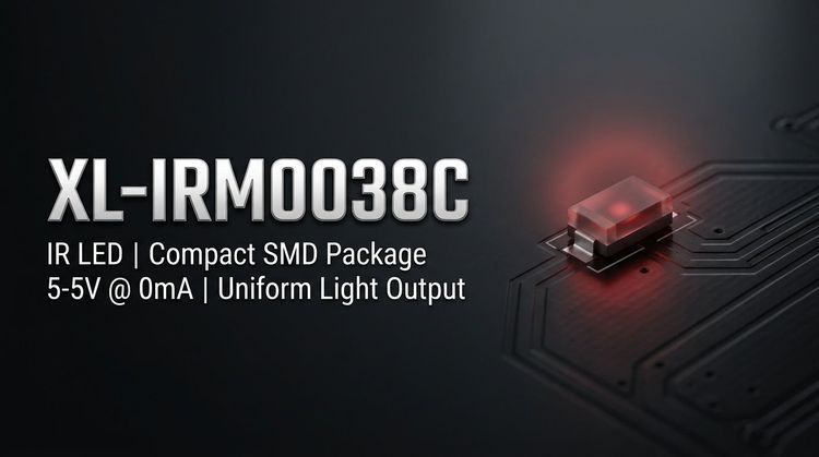
The XL-IRM0038C is a PIN photodiode-based infrared receiver module designed for systems requiring high sensitivity and low power consumption. 📦 It integrates a preamplifier IC and features internal/external shielding to minimize environmental interference from sunlight or fluorescent lighting. Ideal for 37.9kHz carrier frequencies, this component supports TTL and CMOS logic levels with an active-low output, making it suitable for battery-operated remote devices and space-constrained PCB designs.
🔍 Typical Applications
This component is primarily utilized in consumer and industrial sectors requiring reliable wireless infrared communication.
- Home Automation: Air conditioners, fans, heaters, and humidifiers.
- Multimedia Systems: TVs, DVD players, set-top boxes, and vehicle-mounted DVD units.
- Industrial & Peripherals: Instrumentation controllers, induction sanitary ware, and PC peripherals.
- Specialty Electronics: Remote toys, automotive electronics, and financial terminal equipment.
⚡ Key Technical Specifications
These specifications are measured under standard test conditions (Ta=25°C, VDD=5V).
| Parameter | Symbol | Min. | Typ. | Max. | Unit | Test Conditions |
|---|---|---|---|---|---|---|
| Supply Voltage | VDD | 2.7 | - | 5.5 | V | Recommended Range |
| Carrier Frequency | fo | - | 37.9 | - | kHz | Center Frequency |
| BPF Width | fBW | - | 6 | - | kHz | Bandwidth |
| Reception Distance | L (0°) | 15 | 20 | - | m | Standard Test |
| Reception Distance | L (±35°) | 5 | 7 | - | m | Side Angle |
| Low Level Output | VOL | - | - | 250 | mV | Isink=2.0mA |
| Supply Current | ICC | 0.3 | 0.4 | 0.5 | mA | VDD=5V |
⚠️ Absolute Maximum Ratings & Process Limits
Exceeding these values may cause permanent damage to the device. Strict adherence during circuit design and soldering is required.
| Parameter | Symbol | Rating | Unit | Notes |
|---|---|---|---|---|
| Supply Voltage | VDD | 6.0 | V | Do not exceed |
| Operating Temp | Topr | -20 ~ +85 | °C | Ambient range |
| Storage Temp | Tstg | -40 ~ +125 | °C | Storage range |
| Soldering (Wave) | Tsol | 240 | °C | ≤ 6 seconds |
| Soldering (Manual) | Tsol | 300 | °C | ≤ 3 seconds |
📐 Package, Dimensions & Assembly Notes
The XL-IRM0038C utilizes an epoxy resin plastic encapsulation designed for surface mount technology (SMT). Its compact form factor facilitates placement in high-density layouts.
- Type: Epoxy resin semi-spherical package with dual-shielding.
- Dimensions (LxWxH): 4.5mm x 4.0mm x 2.3mm.
- Pin Length: 3.1mm.
- Assembly: Compatible with standard wave soldering (240°C) and manual welding (300°C). Ensure the footprint accounts for the 4.5mm length to avoid clearance issues on the PCB.
🚀 Sourcing & Supply Considerations
When integrating the XL-IRM0038C into your BOM, consider the following supply chain and engineering factors:
- Compliance: Verify批次 certificates for REACH and ROHS to ensure environmental compliance for EU markets.
- Signal Stability: Request test data for reception distance under 40W fluorescent light interference (200±50 Lux) to validate noise immunity.
- Cross-Referencing: Confirm the 37.9kHz carrier frequency compatibility if replacing legacy VS1838 or TSOP series receivers.
❓ FAQ
Q: What is the carrier frequency tolerance for the XL-IRM0038C?
A: The typical carrier frequency is 37.9 kHz with a Band-Pass Filter (BPF) width of 6 kHz.
Q: What is the maximum operating voltage for this IR receiver?
A: The Absolute Maximum Rating for supply voltage is 6.0V, though the recommended working voltage range is 2.7V to 5.5V.
Q: How does the dual-shielding design benefit the circuit?
A: The dual-shielding (internal and external) significantly reduces electromagnetic interference and environmental noise, ensuring stable operation even near fluorescent lights or direct sunlight.
Q: What are the recommended soldering conditions for assembly?
A: For wave soldering, do not exceed 240°C for 6 seconds. For manual welding, the limit is 300°C for 3 seconds.
Q: Is the output compatible with standard microcontrollers?
A: Yes, the output is designed to match TTL and CMOS logic levels, featuring an active-low configuration suitable for direct connection to most MCUs.
Q: What is the typical reception angle and distance?
A: The module offers a reception distance of 15m to 20m at 0 degrees. At a 35-degree angle, the distance reduces to a range of 5m to 7m.