📌 Product Overview
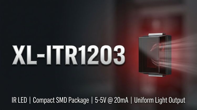
The XL-ITR1203 is a transmissive photoelectric switch integrating a 940nm infrared emitter and a phototransistor detector. 🏗️ This component is specifically engineered to provide high radiant intensity with a low forward voltage, making it suitable for compact, power-sensitive circuit designs.
💡 Targeted primarily at industrial control and consumer electronics, it balances reliability with fast response times. The design focuses on stable detection in "through-beam" applications where physical object presence or position must be registered accurately without contact.
🔎 Typical Applications
Based on the 940nm peak wavelength and fast switching characteristics, the XL-ITR1203 is optimized for the following use cases:
- Currency & Gaming Validation: High sensitivity makes it ideal for coin validators in slot machines and dispensers.
- Office Automation: Integration into fax machines and scanners for paper end detection and skew correction.
- Home Appliances: Non-contact safety sensors and position feedback in small household devices.
- Industrial Automation: Automatic sensors requiring rapid response times (tr/tf ≤ 15μs).
⚙️ Key Technical Specifications
The following electro-optical parameters are critical for assessing signal performance and load driving capability:
| Parameter | Symbol | Test Conditions | Min | Typ | Max | Unit |
|---|---|---|---|---|---|---|
| Forward Voltage | VF | IF = 20mA | -- | 1.2 | 1.6 | V |
| Peak Wavelength | λp | IF = 20mA | -- | 940 | -- | nm |
| Collector Current | IC(ON) | IF=20mA, VCE=5V | 0.2 | 0.5 | 0.95 | mA |
| Saturation Voltage | VCE(SAT) | IC=2mA | -- | -- | 0.4 | V |
| Rise / Fall Time | tr / tf | VCE=5V, IC=1mA | -- | 15 | -- | μs |
💡 Design Note: The voltage grading code (e.g., R2-4) allows tighter binning of VF, while Current Gain (IC6-18) grading ensures consistent sensitivity across batches.
⚠️ Absolute Maximum Ratings & Process Limits
Exceeding these ratings may cause permanent device failure or degradation. These limits define the safety boundaries for both the emitter and detector sides.
| Parameter | Symbol | Rating | Unit | Notes |
|---|---|---|---|---|
| Power Dissipation | PD | 75 | mW | Per Channel (Emitter/Detector) |
| Forward Current | IF | 50 | mA | Continuous |
| Peak Forward Current | IFP | 200 | mA | Pulse width ≤ 100μs |
| Collector-Emitter Voltage | VCEO | 35 | V | Output Detector |
| Operating Temp. | Topr | -25 to +85 | °C | Ambient Range |
| Storage Temp. | Tstg | -40 to +85 | °C |
🔒 Process Alert: The component is Moisture Sensitivity Level (MSL) 2. Floor life after opening the sealed bag is 1 year (factory sealed) or limited exposure time before reflow soldering is required to prevent popcorning damage.
📦 Package, Dimensions & Assembly Notes
The XL-ITR1203 features a compact through-hole package structure designed for PC board mounting.
- Dimensions: The package has a defined profile with a standard tolerance of ±0.3mm unless otherwise specified.
- Soldering: Maximum soldering temperature is 260°C. ⚠️ Critical: The datasheet mandates that soldering must be conducted at a distance of at least 2mm from the resin body for a maximum duration of 5 seconds to prevent thermal damage to the optical epoxy.
- Mounting: Verify slot alignment in the host application to ensure the unobstructed path between the emitter and detector.
📦 Sourcing & Supply Considerations
- Binning Codes: Specific voltage (R2-4) and current gain (IC6-18) codes should be verified against your BOM to ensure consistency.
- Environmental Compliance: The unit is Pb-Free and fully RoHS compliant, suitable for global export markets.
- Authenticity: Procure through authorized channels to avoid counterfeits which often fail to meet the RoHS or MSL specifications.
❓ FAQ
Q: What is the maximum soldering temperature for this component?
A: The maximum allowable soldering temperature is 260°C. However, you must maintain a distance of at least 2mm from the epoxy resin body and limit exposure time to 5 seconds to prevent optical degradation.
Q: What does the "IC6-18" marking signify on the package?
A: This refers to the Current Transfer Ratio (CTR) or Collector Current grading. It guarantees that the collector current (IC) is between 0.3mA and 0.9mA under standard test conditions (IF=20mA, VCE=5V).
Q: Is the XL-ITR1203 suitable for battery-powered devices?
A: Yes. It features a low forward voltage (Typ 1.2V @ 20mA) and low power dissipation (75mW), making it efficient for low-voltage drive applications.
Q: What are the storage requirements before assembly?
A: As the component has a Moisture Sensitivity Level (MSL) of 2, it should be stored in a dry environment. If the moisture barrier bag is exposed to the factory floor, it must be assembled within 1 year to avoid moisture-induced damage during reflow.
Q: Can the emitter handle pulsed current?
A: Yes. The Peak Forward Current (IFP) is rated up to 200mA, provided the pulse width is ≤100μs and the duty cycle is limited to 1%.