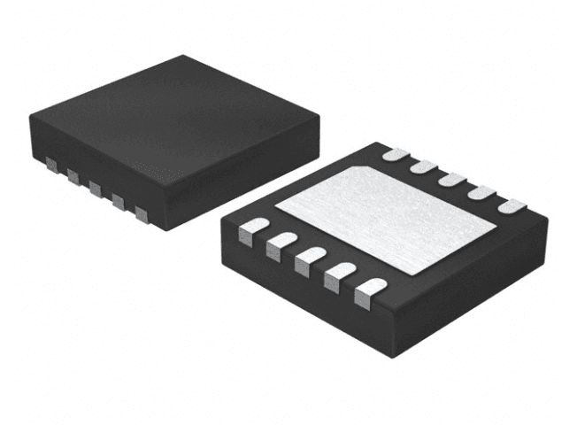
Specifications
| Type | Description |
|---|---|
| Part Number | TPS51206_DDR-Termination |
| Manufacturer | Texas Instruments |
| Product Type | LDO Regulator |
| Category | Power Management |
| Package/Case | 10-pin WSON/SON (DSQ), 2.00 mm x 2.00 mm body |
| Base Part Number | TPS51206 |
| Datasheet Manufacturer | Texas Instruments |
| Regulator Function | Sink/source DDR termination regulator with VTTREF buffered reference |
| Supported DDR Standards | DDR2, DDR3, DDR3L, DDR4 |
| Supply Voltage | 3.1 V min, 6.5 V max |
| Supported Supply Rails | 3.3 V rail and 5 V rail |
| VLDOIN Input Voltage Range | VTT + 0.4 V to 3.5 V |
| VLDOIN Recommended Input Voltage | -0.1 V min, 3.5 V max |
| VTT Output Voltage Range | 0.5 V to 0.9 V |
| VTT Output Voltage | VDDQSNS / 2 |
| VTT Peak Sink/Source Current | 2 A peak sink and source |
| VTT Source Current Limit | 2 A |
| VTT Source Current Limit Condition | VDDQSNS = 1.8 V, VTT = VTTSNS = 0.7 V |
| VTT Sink Current Limit | 2 A |
| VTT Sink Current Limit Condition | VDDQSNS = 1.8 V, VTT = VTTSNS = 1.1 V |
| VTT Output Accuracy | ±20 mV |
| VTT Output Tolerance | -20 mV min, 20 mV max; |IVTT| <= 10 mA, 1.4 V <= VDDQSNS <= 1.8 V |
| VTT Output Tolerance | -30 mV min, 30 mV max; |IVTT| < 1 A, 1.4 V <= VDDQSNS <= 1.8 V |
| VTT Output Tolerance | -40 mV min, 40 mV max; |IVTT| < 2 A, 1.4 V <= VDDQSNS <= 1.8 V |
| VTT Output Tolerance | -20 mV min, 20 mV max; |IVTT| <= 10 mA, 1.2 V <= VDDQSNS <= 1.4 V |
| VTT Output Tolerance | -30 mV min, 30 mV max; |IVTT| < 1 A, 1.2 V <= VDDQSNS <= 1.4 V |
| VTT Output Tolerance | -40 mV min, 40 mV max; |IVTT| < 1.5 A, 1.2 V <= VDDQSNS < 1.4 V |
| VTT Output Capacitor | 10 µF or greater MLCC required; no maximum limit |
| VTTREF Output Voltage | VDDQSNS / 2 |
| VTTREF Accuracy | VDDQ / 2 ±1% |
| VTTREF Output Voltage Tolerance | 49% min, 51% max of VDDQSNS; |IVTTREF| <= 10 mA, 1.5 V <= VDDQSNS <= 1.8 V |
| VTTREF Output Voltage Tolerance | 48.75% min, 51.25% max of VDDQSNS; |IVTTREF| <= 10 mA, 1.2 V <= VDDQSNS < 1.5 V |
| VTTREF Output Voltage Tolerance | 49% min, 51% max of VDDQSNS; |IVTTREF| <= 100 µA, 1.2 V <= VDDQSNS <= 1.8 V |
| VTTREF Source Current | 10 mA |
| VTTREF Source Current Condition | VDDQSNS = 1.8 V, VTTREF = 0 V |
| VTTREF Sink Current | 10 mA |
| VTTREF Sink Current Condition | VDDQSNS = 0 V, VTTREF = 1.8 V |
| VTTREF Capacitor | 0.22 µF to 1 µF MLCC |
| VTTREF Capacitor Condition | Required for stability; VTTREF pin cannot be open |
| S3/S5 Power State Support | High-Z in S3; soft-stop/discharge in S4 and S5 |
| VDD Supply Current in S0 | 170 µA typ |
| VDD Supply Current in S0 Condition | TA = 25°C, VDDQSNS = 1.8 V, no load, S3 = S5 = 5 V |
| VDD Supply Current in S3 | 80 µA typ |
| VDD Supply Current in S3 Condition | TA = 25°C, VDDQSNS = 1.8 V, no load, S3 = 0 V, S5 = 5 V |
| VDD Shutdown Current | 1 µA typ |
| VDD Shutdown Current Condition | TA = 25°C, VDDQSNS = 1.8 V, no load, S3 = S5 = 0 V |
| VLDOIN Supply Current in S0 | 5 µA typ |
| VLDOIN Supply Current in S0 Condition | TA = 25°C, VLDOIN = 1.8 V, no load, S3 = S5 = 5 V |
| VLDOIN Supply Current in S3 | 5 µA typ |
| VLDOIN Supply Current in S3 Condition | TA = 25°C, VLDOIN = 1.8 V, no load, S3 = 0 V, S5 = 5 V |
| VLDOIN Shutdown Current | 5 µA typ |
| VLDOIN Shutdown Current Condition | TA = 25°C, VLDOIN = 1.8 V, no load, S3 = S5 = 0 V |
| VTT Leakage Current | 5 µA typ |
| VTT Leakage Current Condition | TA = 25°C, VTT = VTTREF, S3 = 0 V, S5 = 5 V |
| VTTSNS Input Bias Current | -0.1 µA min, 0.1 µA max |
| VTTSNS Input Bias Current Condition | S3 = 5 V, S5 = 5 V, VTTSNS = VTTREF |
| VTTSNS Leakage Current | -0.1 µA min, 0.1 µA max |
| VTTSNS Leakage Current Condition | S3 = 0 V, S5 = 5 V, VTTSNS = VTTREF |
| VTT Discharge Current | 7 mA typ |
| VTT Discharge Current Condition | TA = 25°C, VTT = 0.5 V, S3 = S5 = VDDQSNS = 0 V |
| VTTREF Discharge Current | 1.3 mA typ |
| VTTREF Discharge Current Condition | TA = 25°C, S3 = S5 = 0 V, VTTREF = 0.5 V |
| VDDQSNS Input Current | 30 µA typ |
| VDDQSNS Input Current Condition | VDDQSNS = 1.8 V |
| VDD UVLO Wakeup Threshold | 2.67 V min, 2.90 V typ, 3.00 V max |
| VDD UVLO Hysteresis | 0.2 V typ |
| S3/S5 Low-Level Voltage | 0.5 V max |
| S3/S5 High-Level Voltage | 1.8 V min |
| S3/S5 Hysteresis Voltage | 0.3 V typ |
| S3/S5 Input Leakage Current | -1 µA min, 1 µA max |
| Operating Free-Air Temperature | -40°C min, 105°C max |
| Operating Junction Temperature | -40°C min, 150°C max |
| Storage Temperature | -55°C min, 150°C max |
| Overtemperature Shutdown | 150°C typ |
| Overtemperature Shutdown Condition | Ensured by design, not production tested |
| Overtemperature Hysteresis | 10°C typ |
| Overtemperature Hysteresis Condition | Ensured by design, not production tested |
| ESD Rating HBM | ±2000 V |
| ESD Rating HBM Condition | Human-body model per ANSI/ESDA/JEDEC JS-001 |
| ESD Rating CDM | ±500 V |
| ESD Rating CDM Condition | Charged-device model per JEDEC JESD22-C101 |
| Junction-to-Ambient Thermal Resistance | 70.3°C/W |
| Junction-to-Ambient Thermal Resistance Condition | DSQ WSON, 10 pins |
| Junction-to-Case Top Thermal Resistance | 46.3°C/W |
| Junction-to-Case Top Thermal Resistance Condition | DSQ WSON, 10 pins |
| Junction-to-Board Thermal Resistance | 33.8°C/W |
| Junction-to-Board Thermal Resistance Condition | DSQ WSON, 10 pins |
| Junction-to-Case Bottom Thermal Resistance | 16.3°C/W |
| Junction-to-Case Bottom Thermal Resistance Condition | DSQ WSON, 10 pins |
| Thermal Pad | Solder to ground plane for increased thermal performance |
| Datasheet Status | request_only |
Product Overview
TPS51206_DDR-Termination is classified as a Power_IC DDR termination regulator for memory power systems. The extracted datasheet facts identify the base part as TPS51206 and describe a sink/source DDR termination regulator with a buffered VTTREF reference for DDR2, DDR3, DDR3L, and DDR4 applications.
The regulator operates from a 3.1 V to 6.5 V VDD supply and supports 3.3 V and 5 V rails. VTT is regulated at VDDQSNS/2, with a 0.5 V to 0.9 V output range and 2 A peak sink/source capability. VTTREF is also VDDQSNS/2 and is specified for 10 mA source and sink current.
The package is a 10-pin WSON/SON (DSQ) with a 2.00 mm x 2.00 mm body. The VTT pin requires a 10 µF or greater MLCC, VTTREF requires a 0.22 µF to 1 µF MLCC, and the thermal pad is specified for soldering to the ground plane to improve thermal performance.
Key Features
- Sink/source DDR termination regulator with buffered VTTREF reference
- Supports DDR2, DDR3, DDR3L, and DDR4 memory rails
- Operates from 3.1 V to 6.5 V VDD
- Supports 3.3 V and 5 V supply rails
- VTT output range is 0.5 V to 0.9 V
- VTT and VTTREF track VDDQSNS divided by two
- 2 A peak VTT sink and source capability
- S3 high-Z and S4/S5 soft-stop discharge support
- 10-pin 2 mm x 2 mm WSON/SON DSQ package
- Thermal pad specified for soldering to ground plane
Typical Applications
- DDR2 memory termination
- DDR3 memory termination
- DDR3L memory termination
- DDR4 memory termination
- VTT bus power supplies
- Memory power supply rails
- S3 and S5 power-state systems
- 3.3 V rail systems
- 5 V rail systems
Procurement Notes
When requesting a quote for TPS51206_DDR-Termination, buyers should confirm the manufacturer, package or case, required quantity, target date code, compliance documents, packing method, destination country and expected delivery schedule.
If alternatives are acceptable, buyers should share the approved vendor list, required electrical or optical limits, package constraints and qualification requirements. Any alternative part should be reviewed by the buyer's engineering team before production use.
For power IC and power device sourcing, voltage rating, current rating, power dissipation, package thermal performance, protection features, qualification grade and application conditions should be reviewed before approval.
FAQ
What is the regulated VTT output voltage?
The extracted electrical characteristics specify VTT as VDDQSNS divided by two. The listed VTT termination output voltage range is 0.5 V to 0.9 V.
Which DDR memory standards are supported?
The extracted facts list DDR2, DDR3, DDR3L, and DDR4 support for memory power supplies and the VTT bus.
What output capacitors are required for stability?
The VTT pin requires a 10 µF or greater MLCC with no maximum limit. The VTTREF pin requires a 0.22 µF to 1 µF MLCC and cannot be left open.
What package is specified for this regulator?
The package is specified as a 10-pin WSON/SON DSQ package with a 2.00 mm x 2.00 mm body. Thermal data is listed for the DSQ WSON 10-pin package.
Technical Review & Sourcing Note
Prepared by LDeepAI Component Sourcing Team. Reviewed for RFQ, documentation and alternative sourcing use. Last updated: June 30, 2026.
This page is based on manufacturer datasheet information and LDeepAI sourcing review. Specifications should be verified against the official manufacturer datasheet before final procurement or design approval. Final electrical, optical and reliability approval should be confirmed by the buyer's engineering team.