
Specifications
| Type | Description |
|---|---|
| Part Number | XL-TD3216IRC-940 |
| Manufacturer | XINGLIGHT |
| Product Type | SMD LED |
| Category | LED |
| Package Case | 1206 SMD, 3.2 x 1.6 x 1.96 mm |
| Outline Dimensions | 3.2 x 1.6 x 1.96 mm; L/W/H |
| Package Size | 1206; SMD infrared emitter |
| Emission Color / Wavelength | Infrared 940 nm; transparent/water clear colloid |
| Moisture Sensitivity Level | MSL 3 |
| Power Dissipation | 50 mW max; Ta=25°C |
| Peak Forward Current | 100 mA max; pulse width <=0.1 ms, duty <=1/10, Ta=25°C |
| Forward Working Current | 30 mA max; Ta=25°C |
| Reverse Voltage | 5 V max; Ta=25°C |
| Operating Ambient Temperature | -40°C to +85°C; Ta=25°C absolute maximum ratings table |
| Storage Ambient Temperature | -40°C to +85°C; Ta=25°C absolute maximum ratings table |
| Reflow Soldering Condition | 260°C, 6 s; absolute maximum welding conditions |
| Manual Soldering Condition | 300°C, 3 s; absolute maximum welding conditions |
| Radiation Intensity | 15 min, 20 typ, 30 max mW/sr; IF=20 mA, Ta=25°C |
| Half Intensity Angle | 30 deg typ; 2θ1/2, IF=20 mA, Ta=25°C |
| Dominant Wavelength | 940 nm typ; λD, IF=20 mA, Ta=25°C |
| Spectral Half Width | 40 nm typ; Δλ, IF=20 mA, Ta=25°C |
| Forward Voltage | 1.2 typ, 1.5 max V; IF=20 mA, Ta=25°C |
| Reverse Current | 1 uA max; VR=5 V, Ta=25°C |
| Radiation Intensity Bin P1-5 | 15 to 20 mW/sr; IF=20 mA |
| Radiation Intensity Bin P1-6 | 20 to 25 mW/sr; IF=20 mA |
| Radiation Intensity Bin P1-7 | 25 to 30 mW/sr; IF=20 mA |
| Forward Voltage Bin N17-2 | 1.1 to 1.2 V; IF=20 mA |
| Forward Voltage Bin N17-3 | 1.2 to 1.3 V; IF=20 mA |
| Forward Voltage Bin N17-4 | 1.3 to 1.4 V; IF=20 mA |
| Forward Voltage Bin N17-5 | 1.4 to 1.5 V; IF=20 mA |
| Wavelength Bin IR02 | 930 to 940 nm; IF=20 mA |
| Wavelength Bin IR03 | 940 to 950 nm; IF=20 mA |
| Wavelength Bin IR04 | 950 to 960 nm; IF=20 mA |
| Dimension Tolerance | ±0.25 mm; unless otherwise noted |
| Recommended Maximum Welding Temperature | 240±5°C for 6 s; product soldering guideline |
| Reflow Soldering Cycles | 2 times max; reflow soldering guideline |
| Opened Package Floor Life | 168 hours / 7 days; store at <=30°C and <=40%RH after opening |
| Baking Condition | 60±5°C for 24 hours; if moisture absorbent material faded or storage time exceeded |
| Datasheet Status | request_only |
Product Overview
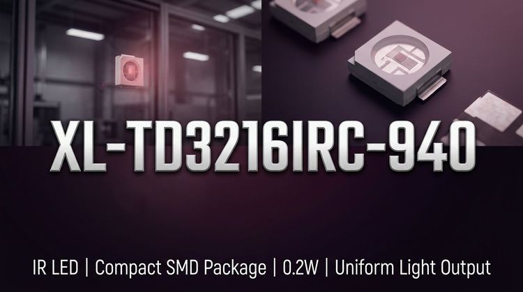
XL-TD3216IRC-940 is a XINGLIGHT 940 nm infrared emitter diode supplied as a 1206 SMD LED. The package size is 3.2 x 1.6 x 1.96 mm, with a transparent/water clear colloid emission description and a general dimension tolerance of ±0.25 mm unless otherwise noted.
At IF=20 mA and Ta=25°C, the diode is specified with 15 mW/sr minimum, 20 mW/sr typical, and 30 mW/sr maximum radiation intensity. The typical dominant wavelength is 940 nm, spectral half width is 40 nm, half intensity angle is 30 degrees, and forward voltage is 1.2 V typical with a 1.5 V maximum. Reverse current is rated at 1 uA maximum at VR=5 V.
Assembly and handling limits include MSL 3, 260°C for 6 s absolute maximum reflow soldering condition, 300°C for 3 s manual soldering condition, and a recommended maximum welding temperature of 240±5°C for 6 s. Reflow soldering is limited to 2 cycles, and opened package floor life is 168 hours / 7 days at <=30°C and <=40%RH.
Key Features
- 940 nm infrared emission wavelength
- 1206 SMD package for compact board mounting
- 3.2 x 1.6 x 1.96 mm outline dimensions
- 20 mW/sr typical radiation intensity at 20 mA
- 30 degree typical half intensity angle
- 1.2 V typical forward voltage at 20 mA
- 30 mA maximum forward working current
- -40°C to +85°C operating ambient range
- MSL 3 moisture sensitivity level
- Two maximum reflow soldering cycles
Typical Applications
- Infrared sensing circuits
- Short-range optical links
- IR emitter modules
- Object detection assemblies
- Photo-interrupter light sources
- Compact SMD infrared boards
- 940 nm receiver pairing
Procurement Notes
When requesting a quote for XL-TD3216IRC-940, buyers should confirm the manufacturer, package or case, required quantity, target date code, compliance documents, packing method, destination country and expected delivery schedule.
If alternatives are acceptable, buyers should share the approved vendor list, required electrical or optical limits, package constraints and qualification requirements. Any alternative part should be reviewed by the buyer's engineering team before production use.
For LED and optoelectronic sourcing, brightness bin, wavelength or color temperature bin, forward voltage range, viewing angle, moisture sensitivity level and soldering process limits may affect final selection, availability and lead time.
Alternatives
Candidate
EVERLIGHT
HIR26-21C/L423/CT
These are candidate cross-reference options. Share quantity, application, approved vendor list, package limits and optical/electrical requirements before sample or quote review.
Request Sample / Quote ReviewApplication Verification Recommended
Related Technical Articles
FAQ
What type of LED is XL-TD3216IRC-940?
XL-TD3216IRC-940 is a XINGLIGHT 940 nm infrared emitter diode in the LED category. It uses a 1206 SMD package with 3.2 x 1.6 x 1.96 mm outline dimensions.
What optical output is specified at 20 mA?
At IF=20 mA and Ta=25°C, the radiation intensity is specified as 15 mW/sr minimum, 20 mW/sr typical, and 30 mW/sr maximum. The typical half intensity angle is 30 degrees.
What forward voltage range applies to this infrared emitter?
The electrical characteristics list 1.2 V typical and 1.5 V maximum forward voltage at IF=20 mA and Ta=25°C. Forward voltage bins span 1.1 V to 1.5 V across N17-2 through N17-5.
What assembly limits are listed for soldering?
The absolute maximum welding conditions list 260°C for 6 s reflow soldering and 300°C for 3 s manual soldering. The product soldering guideline recommends 240±5°C for 6 s and limits reflow soldering to two cycles.
Technical Review & Sourcing Note
Prepared by LDeepAI Component Sourcing Team. Reviewed for RFQ, documentation and alternative sourcing use. Last updated: July 28, 2026.
This page is based on manufacturer datasheet information and LDeepAI sourcing review. Specifications should be verified against the official manufacturer datasheet before final procurement or design approval. Final electrical, optical and reliability approval should be confirmed by the buyer's engineering team.