📌 Product Overview
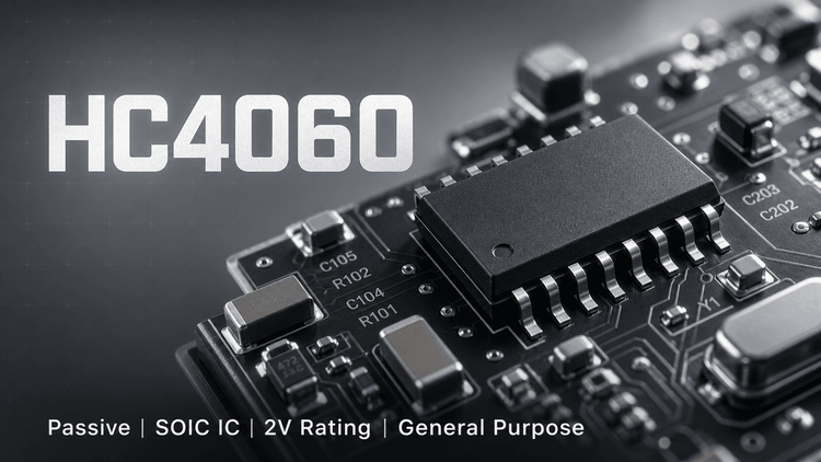
The SN74HC4060 is a high-speed silicon-gate CMOS device integrating a 14-stage ripple-carry counter and an oscillator section. Designed for applications requiring long-time delays or frequency division, it allows designers to implement either RC or crystal oscillator circuits directly on-chip. For OEMs and EMS providers, the critical selection factors are its wide voltage range (2V to 6V) and low power consumption, making it ideal for battery-powered industrial controllers and timing modules.
🎯 Typical Applications & Design Context
- ✨ Power Management & Timing: Essential for watchdog timers and long-period interval timing in industrial equipment due to its on-chip oscillator capability.
- ⚡ Consumer Electronics: Used in remote control transmitters and appliance timers where low current draw (80-µA max) extends battery life.
- 💡 Frequency Division: Effective in clock generation and frequency synthesizing systems where driving up to 10 LSTTL loads is required.
📊 Key Technical Specifications
| Parameter | Value/Condition | Notes |
|---|---|---|
| Supply Voltage Range | 2 V to 6 V | Flexible design for 3.3V or 5V systems |
| Max Low Power Supply Current | 80 µA (at 5V) | Critical for battery-operated devices |
| Output Drive Current | ±4 mA (at 5V) | Sufficient to drive LSTTL loads |
| Operating Temp (Industrial) | -40°C to 85°C | Standard SN74HC series range |
| Oscillator Type | RC or Crystal | Configurable via external components |
⚠️ Absolute Maximum Ratings & Process Limits
Exceeding these ratings during mass production or testing will cause permanent damage.
| Parameter | Value | 🚨 Mass Production Failure Risk |
|---|---|---|
| Supply Voltage (VCC) | -0.5 V to 7 V | > 7V input spikes during PCB hot-swapping can cause immediate oxide layer breakdown. |
| Input Clamp Current | ±20 mA | Overcurrent can bond wire fuse or damage ESD structures; verify signal source impedance. |
| Continuous Output Current | ±25 mA | Exceeding this leads to thermal runaway and output latch-up, particularly when driving capacitive loads > 5000pF. |
| Storage Temperature | -65°C to 150°C | Baking required if moisture exposure exceeds MSL limits before reflow. |
🧩 Package, Dimensions & Assembly Notes
- Package Variety: Available in PDIP (N), SOIC (D), SSOP (DB), TSSOP (PW), and SOP (NS) packages.
- SMT Validation: The TSSOP (PW) and SSOP (DB) packages offer high density (Reel of 2500/2000) but require precise stencil aperture design to avoid tombstoning.
- Thermal Management: The thermal impedance (θJA) varies significantly (e.g., 82°C/W for DB package vs. 108°C/W for PW). Layouts must ensure adequate copper pour under the GND pin to dissipate heat during high-frequency oscillation.
🔍 Procurement & Sourcing Insights
- 💡 Lifecycle Status: Originally released in 1982, this is a mature, stable component. However, specific package options (e.g., CDIP J) may be listed as "Not for New Design."
- 🚀 Sourcing Strategy: While TI is the primary source, cross-reference to NXP or ON Semiconductor 74HC4060 is common. Verify pin-to-pin compatibility, specifically the functionality of Pin 1 (Q vs NC), which varies by manufacturer.
- 🔒 Authenticity: Given the age of the datasheet (Rev 2003), beware of recycled or pulled parts in the open market. Always trace back to authorized franchised distributors to avoid counterfeit silicon.
❓ FAQ
Q: Can I use a ceramic resonator with the HC4060 oscillator section?
A: The datasheet specifies RC or Crystal configurations. While ceramic resonators can sometimes function, they require specific load capacitance values not fully characterized in this datasheet, risking start-up failure in mass production.
Q: What is the difference between the SN54 and SN74 series?
A: SN54 (e.g., SNJ54HC4060J) is rated for -55°C to 125°C (Military/Aerospace) and often comes in ceramic packages. SN74 is for commercial/industrial use (-40°C to 85°C) in plastic molding.
Q: Why did my counter reset unexpectedly during testing?
A: Check the Clear (CLR) pin. It is active-high. Any noise spike > 0.8 x VCC on this line will reset the counter. Ensure proper filtering or pull-down on the CLR trace.
Q: Are the TSSOP and SSOP packages pin-compatible?
A: No. While both are SMT, the pin pitch (0.65mm vs 0.635mm) and footprint differ. You cannot replace a DB (SSOP) with a PW (TSSOP) without modifying the PCB land pattern.