📌 Product Overview
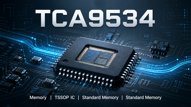
The TCA9534 from Texas Instruments is a low-voltage, 8-bit I/O expander designed to extend the GPIO capabilities of processors via the I²C/SMBus interface. It is not a memory component; it is a critical Logic / Interface IC used for system control. This device is ideal for designs where the host MCU is GPIO-constrained, offering bidirectional data transfer with an operating voltage range of 1.65 V to 5.5 V. It features an active-low interrupt output and three hardware address pins, enabling up to 8 devices on a single bus. Key selection variables include 5-V tolerant I/Os, latched outputs for direct LED driving, and support for Fast-mode (400 kHz) I²C signaling.
🎯 Typical Applications & Design Context
💡 Target Scenarios: Servers, Telecom Routers, Industrial Automation, Gaming Consoles.
- GPIO Expansion: Essential for processors (e.g., low-power MCUs) with limited I/O pins, allowing control of peripheral loads like fans, LEDs, and switches.
- Level Shifting & Mixed Voltage: With a supply range of 1.65V to 5.5V and 5-V tolerant inputs, it bridges logic level differences between 1.8V/3.3V hosts and 5V peripheral buses.
- Power Management: Supports low standby current, making it suitable for battery-powered or energy-efficient personal electronics.
- Industrial Control: The noise filter on SCL/SDA inputs and internal Power-On Reset (POR) ensure reliability in electrically noisy environments like factory floors.
📊 Key Technical Specifications
| Parameter | Value/Condition | Engineering Note |
|---|---|---|
| Supply Voltage Range | 1.65 V to 5.5 V | Flexible power domain routing; supports dual-voltage systems. |
| I/O Port Logic | 5-V Tolerant | P0–P7 can withstand 5V inputs even when VCC is 1.65V (interface compatibility). |
| I²C Speed | 100 kHz (Std) / 400 kHz (Fast) | Compatible with most standard MCU I²C clocks; no glitch on power-up. |
| Interrupt Output | Open-Drain, Active-Low | Asynchronous alert to master; requires external pull-up resistor. |
| Addressing | 3 Hardware Pins (A0-A2) | Allows up to 8 identical devices on the same bus without software conflict. |
| ESD Protection | ±2000V (HBM) | High robustness for handling during PCB assembly and field servicing. |
⚠️ Absolute Maximum Ratings & Process Limits
| Parameter | Limit | E-E-A-T Validation Insight |
|---|---|---|
| Supply Voltage (VCC) | –0.5 V to 6.0 V | ⚠️ Latch-up Risk: Exceeding 6.0 V risks permanent silicon damage. During thermal cycling or power sequencing, ensure transients do not spike above this limit. |
| Input Voltage (VI) | –0.5 V to 6.0 V | Applies to all pins including SDA/SCL/INT. Overvoltage here can cause EOS (Electrical Overstress) failures in the field. |
| Continuous Output Current | ±25 mA per I/O | 🔥 Thermal Warning: While the datasheet lists this, driving LEDs near 25mA on multiple ports simultaneously will exceed the package power dissipation limit. Derating is mandatory for mass production stability. |
| Operating Temp | –40 °C to 125 °C (Ambient) | Industrial-grade validation required. Ensure the PCB stack-up dissipates heat effectively if the ambient environment approaches 85°C+. |
🧩 Package, Dimensions & Assembly Notes
📦 Available Packages:TSSOP (16) (5.00mm × 4.40mm) and SOIC (16) (10.30mm × 7.50mm).
- Soldering & Layout: The thermal pad (if present in newer revisions) or the ground pin must be well-soldered to dissipate heat.
- ESD Handling: Although rated for 2000V HBM, standard handling precautions (ESD straps, ionizers) are mandatory during SMT placement due to the high sensitivity of I²C interface pins.
- Moisture Sensitivity: Verify the MSL (Moisture Sensitivity Level)—typically Level 3 for these packages. If the floor life is exceeded (168 hours @ 30°C/60% RH), baking is required before reflow to prevent "popcorning" or internal delamination.
🔍 Procurement & Sourcing Insights
🚀 Supply Chain Reality Check:
- Lifecycle Status: The TCA9534 is a mature, stable product from TI, generally not listed as "Not for New Design" (NRND), but always verify the latest status via TI.com or LDeepAI tools.
- Fake/Counterfeit Risk: High in open markets (Huaqiangbei). Authentic TI parts have specific laser marking etches; counterfeits often have "sandy" laser textures or inconsistent font spacing.
- Alternative Validation: Direct pin-to-pin replacements exist (e.g., NXP PCA9554). ⚠️ Critical Trap: Do not swap blindly. Verify the Reset State behavior. The TCA9534 defaults to inputs with high impedance; some alternatives may have different default polarities causing bus conflicts during system boot.
- Availability: Generally stable, but geopolitical shifts can lead to 20-30 week lead times for specific SOIC packages.
❓ FAQ
Q: Can I use the TCA9534 to drive LEDs directly?
A: Yes, but with caution. The datasheet mentions "High-Current Drive" latched outputs (typically 10mA to 25mA). However, you must calculate the total power dissipation of the package. If you light up 8 LEDs at 20mA simultaneously, the heat generated in the TSSOP package may exceed its thermal limits, reducing reliability. Use current-limiting resistors and consider the duty cycle.
Q: What is the main risk when swapping this part with a competitor's I/O expander?
A: The I2C Address Map and Internal Register Addresses. While the I²C protocol is standard, the register hex codes for configuration (Input/Output) and Polarity often differ between brands. A software driver written for the TCA9534 will fail to control an NXP or ON Semi part correctly without code modification.
Q: The INT pin is "Open-Drain." Do I need a pull-up resistor?
A: Yes. The interrupt pin (INT) is open-drain active-low. It cannot drive a logic High on its own. You must connect a pull-up resistor (typically 1kΩ to 10kΩ) to the VCC rail of the host MCU for the interrupt signal to function correctly.
Q: How do I handle the address pins (A0-A2) during PCB assembly?
A: These pins determine the I2C slave address. If left floating, they may float to a random logic state, causing address conflicts on the bus. For mass production, do not leave A0-A2 floating. Tie them firmly to GND or VCC via PCB traces. Do not rely on "No-Pop" (resistor) options for address selection unless explicitly designed, as unconnected pins are susceptible to ESD noise.