📌 Product Overview
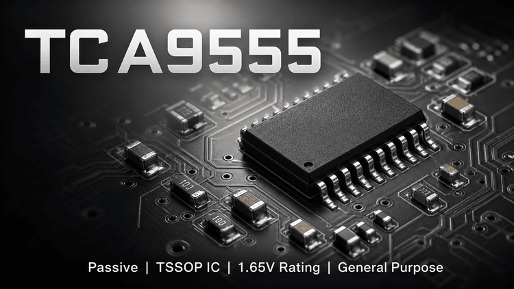
The TCA9555 is a 16-bit General Purpose Input/Output (GPIO) expander utilizing the I²C interface. It is designed to increase the I/O capacity of microcontrollers (MCUs) that lack sufficient pins. 📌 Core Identity: It bridges the gap between the limited GPIO resources of modern processors and the peripheral requirements of complex systems (keypads, LEDs, sensors).
Unlike simple digital logic, this device features configurable registers (Input, Output, Polarity Inversion, and Configuration), allowing system software to dynamically change pin directions. It operates from 1.65V to 5.5V, making it ideal for interfacing between low-voltage MCUs and higher voltage peripherals. 💡 Critical Selection Variable: Engineers must prioritize the interrupt mechanism and I/O voltage tolerance when designing for battery-powered or mixed-voltage industrial control systems.
🎯 Typical Applications & Design Context
- Servers & Routers: Used for Hardware Management (LED status, fan control) where the main BMC/processor lacks physical pins.
- Industrial Automation: Interfaces GPIO-limited PLCs or MCUs with sensor arrays and relay banks.
- Personal Electronics: Expands limited mobile processor pins for keypad matrices or headset detection.
- Why it fits: The 400kHz Fast-Mode I²C capability allows rapid status updates without polling, while the 5-V Tolerant I/O Ports allow direct connection to legacy 5V logic without level shifters, reducing BOM cost.
📊 Key Technical Specifications
| Parameter | Value/Condition | Engineering Note |
|---|---|---|
| Supply Voltage (VCC) | 1.65 V to 5.5 V | Wide range supports 3.3V and 5V bus systems. |
| I²C Speed | 400 kHz (Fast Mode) | Ensures responsive control in high-speed data paths. |
| I/O Current (Sink) | 10 mA (Typ) | Strong Drive: Capable of directly driving standard LEDs without external buffers. |
| Interrupt Response | Open-Drain Active-Low | Provides hardware notification to the host, reducing software polling overhead. |
| Standby Current | 3.5 µA Max | Critical for Battery Designs: Extremely low leakage when idle. |
⚠️ Absolute Maximum Ratings & Process Limits
| Parameter | Rating | Failure Impact (E-E-A-T Insight) |
|---|---|---|
| VCC Range | -0.5 V to 6.5 V | Exceeding 6.5V risks immediate oxide breakdown of the CMOS structure. |
| Input Voltage (VI) | -0.5 V to 6.5 V | Even if VCC is off, applying >6.5V to pins can trigger latch-up. |
| Continuous Output Current | 25 mA per pin | Exceeding this causes metal melt/fusing in the bond wires. ⚠️ Thermal Warning: Total current is limited by package heating, not just individual limits. |
| Operating Temp (Junction) | -40°C to +125°C | High-drive LED applications will push junction temps; verify thermal derating. |
🧩 Package, Dimensions & Assembly Notes
The TCA9555 is available in TSSOP (24-pin), SSOP (24-pin), and VQFN/WQFN (4mm x 4mm) packages.
- VQFN/WQFN (RTW/RGE): These packages feature an exposed thermal pad on the bottom.
- Assembly: The thermal pad must be soldered to the PCB ground plane. ⚠️ Failure Mode: Skipping the thermal pad soldering creates a high-resistance thermal path, causing the device to overheat under maximum I/O load and reset unexpectedly.
- SMT Validation: Ensure the stencil design accounts for the thermal pad aperture to prevent solder voiding (>50% voiding can compromise thermal performance).
🔍 Procurement & Sourcing Insights
- Supply Chain Risk: This device is originally Texas Instruments (TI), but the prompt lists "International Rectifier" (Infineon). Verify the exact logo and date code on the reel. Huaqiangbei markets may mix similar-marked I2C expanders.
- Alternative Validation: Common alternatives include PCA9555 (NXP) and PCAL9555. While the I2C address map is standard, the Reset polarity and Internal Pull-up strengths differ. 🛠️ Validation Step: Cross-reference the "Input High" leakage current when swapping brands to ensure bus stability.
- Traceability: For industrial equipment, demand reels with intact Lot Codes. Fake lots often have misaligned laser marking or inconsistent font weight on the package body.
❓ FAQ
Q: Can the TCA9555 directly drive an LED?
A: Yes. The datasheet specifies a "High-Current Drive Capability" (typically 10mA). However, calculate the total power dissipation. If all 16 pins drive LEDs simultaneously, the device may exceed its thermal limits. Use external buffers if driving more than 4-5 high-brightness LEDs at once.
Q: What is the difference between TCA9555 and PCA9555?
A: They are largely pin-to-pin compatible, but the TCA9555 generally specifies wider voltage tolerance on I/O pins when the device is unpowered (5-V Tolerant), whereas some older NXP PCA9555 revisions are strictly 3.3V tolerant. Verify the "VI" spec in the Absolute Maximum Ratings table during cross-sourcing.
Q: My system keeps resetting randomly. Is this the TCA9555?
A: Likely thermal shutdown. If you are using the VQFN package, check if the central thermal pad was properly soldered. Also, check if the total current from all outputs (IOL) sums up near the 100mA range; this causes localized heating, triggering the internal thermal protection.
Q: How does the INT pin behave during a power-on reset (POR)?
A: The datasheet notes that I/Os default to inputs. The INT pin is Open-Drain. If the MCU initializes slowly, the INT line may float. Ensure your MCU has a weak pull-up on the INT line to prevent false interrupts during the boot sequence.