📌 Product Overview
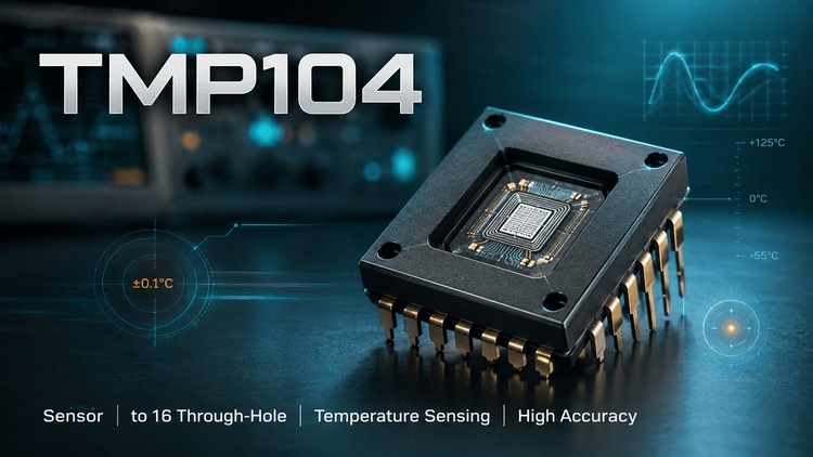
The TMP104 from Texas Instruments is a low-power digital temperature sensor in a 4-ball WCSP (DSBGA) package measuring 1.20 mm × 1.00 mm. It provides 8-bit resolution with ±0.5°C typical accuracy from –10°C to +100°C and communicates over a proprietary SMAART Wire™ UART-style interface.
Its defining capability is Multiple Device Access (MDA): up to 16 devices can share one bus in parallel or daisy-chain, letting a single host read multiple temperature zones without individual addressing. Selection decisions hinge on interface compatibility (not I²C), supply range (1.4–3.6V), and WCSP assembly readiness.
🎯 Typical Applications & Design Context
- Handsets and wearables — the 0.8 × 1.0 mm footprint fits inside dense PCB zones where no other sensor package fits
- Notebooks and tablets — multiple thermal zones (battery, SoC, chassis) monitored from one host port
- Multi-zone systems — MDA and daisy-chain eliminate per-device addressing, cutting firmware complexity and GPIO usage
The TMP104 suits these scenarios because power draw is minimal (3 µA active at 0.25 Hz, 1 µA shutdown) and the WCSP package minimizes board area. Note: the SMAART Wire interface is not I²C/SMBus-compatible—firmware must implement the UART-style protocol.
📊 Key Technical Specifications
| Parameter | Value | Notes |
|---|---|---|
| Resolution | 8 bits | 1°C steps |
| Accuracy | ±0.5°C typ | –10°C to +100°C |
| Supply range | 1.4V – 3.6V | Abs. max 4V |
| Active current | 3 µA | at 0.25 Hz |
| Shutdown current | 1 µA | |
| Interface | SMAART Wire™ | UART-style, daisy-chain, MDA |
| Bus capacity | Up to 16 devices | |
| Operating range | –40°C to +125°C | |
| Package | WCSP-4 (DSBGA) | 1.20 × 1.00 mm |
⚠️ Absolute Maximum Ratings & Process Limits
| Rating | Min | Max | Unit |
|---|---|---|---|
| Supply voltage | — | 4.0 | V |
| Input voltage | –0.3 | (V+)+0.5, ≤4 | V |
| Operating temperature | –55 | +150 | °C |
| Junction temperature | — | +150 | °C |
| Storage temperature | –60 | +150 | °C |
💡 E-E-A-T field note: The 188.5 °C/W θJA of the 4-ball WCSP means the die tracks ambient, not board temperature—the chip will self-heat only if adjacent loads dump heat into shared copper. In SMT, WCSP parts tolerate zero rework: a single over-profile cycle (>260°C peak or slow ramp) can flip solder balls or crack the die, and there is no way to visually inspect the joints under the package. Limit to one reflow pass and define X-ray/AOI sampling before mass production.
🧩 Package, Dimensions & Assembly Notes
- Package: WCSP-4 (DSBGA-4), YFF, 0.8 × 1.0 mm (±5%), body 1.20 × 1.00 mm
- Pinout: A1 = V+, A2 = GND, B1 = TX (push-pull output), B2 = RX
- Assembly: Requires standard WCSP flux dipping or print-through stencil; nsold paste ≤ 100 µm thickness recommended
- PCB footprint must match TI's DSBGA-4 land pattern exactly—0.4 mm ball pitch tolerates no layout improvisation
- TX is push-pull, so no pull-up resistors are needed on the bus; verify host RX threshold levels at 1.4V low-voltage operation
🔍 Procurement & Sourcing Insights
- 🚀 Lifecycle & sourcing: TMP104 is an older TI catalog part—confirm active status and remaining stock depth before design-in; TI franchised distribution lead times can stretch in tight cycles.
- 🔒 Traceability: WCSP dies are easy to remark or reclaim—insist on factory-sealed, date-coded reels with TI certificate of conformance, especially via broker channels.
- 📈 Sample/MOQ: Samples and small reels are usually available for EV builds; plan MSL handling (bake/reel integrity) before pilot runs.
- ✅ Alternative validation: Any substitute must match SMAART Wire protocol, MDA behavior, and DSBGA-4 footprint—no I²C drop-in exists. Contact LDeepAI for sourcing and cross-reference screening.
❓ FAQ
Q: Can TMP104 replace a TMP102 or other I²C sensor?
A: No. The SMAART Wire interface is UART-style and not I²C-compatible. Firmware and bus topology must be redesigned; no drop-in I²C substitute exists.
Q: How many TMP104s can one host support?
A: Up to 16 devices can share a bus via parallel or daisy-chain configuration using MDA commands.
Q: What supply voltage range does it need?
A: 1.4V to 3.6V operation; absolute maximum is 4V. Exceeding 4V risks permanent damage—verify rail sequencing in multi-supply designs.
Q: What are the SMT risks with the WCSP package?
A: Solder joints are invisible post-reflow. One reflow pass only, controlled profile, and X-ray sampling are essential; rework is effectively impossible.
Q: Why is my TMP104 reading offset from board temperature?
A: With 188.5 °C/W θJA and a tiny die, the sensor reads ambient/air temperature well but is highly affected by nearby heat sources on shared copper planes.
Q: How should incoming goods be verified?
A: Check date codes, reel sealing, and TI CoC; avoid mixing lot codes in one production run without first-article validation.