📌 Product Overview
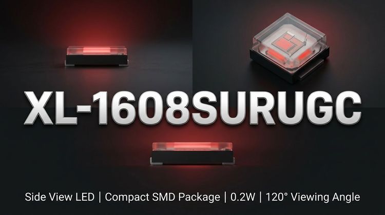
The XL-1608SURUGC is a dual-color SMD LED component designed by XINGLIGHT. 💡 It integrates Red and Green light emitters into a single 1608 metric package (1.6mm x 0.8mm x 0.6mm) with a transparent water-clear lens. This component is engineered for high-density PCB layouts requiring multi-color status indication or pixel arrays without increasing footprint size. It utilizes an environmentally friendly process compliant with ROHS directives and supports standard SMT automated production lines.
🚀 Typical Applications
Based on its 1608 form factor and bi-color optical characteristics, this component is suitable for the following scenarios:
- Electronic Display Screens: Ideal for status indicators, low-resolution pixel arrays, and dashboard instrumentation.
- Consumer Electronics: 📱 Backlighting for mobile phones, digital products, and handheld device keypads.
- Status Indication: Pilot lamps for power, charging states, or operational modes in white goods and industrial control panels.
- Compact Lighting: Indoor accent lighting and auxiliary indicators where space constraints are critical.
⚙️ Key Technical Specifications
💡 The following table outlines the electro-optical performance under standard test conditions (Ta=25°C). It highlights the voltage differential between the Red and Green chips, a critical factor for driver circuit design.
| Parameter | Symbol (Red) | Typ Value (Red) | Symbol (Green) | Typ Value (Green) | Unit |
|---|---|---|---|---|---|
| Forward Voltage | VF | 2.1 | VF | 2.9 | V |
| Luminous Intensity | IV | 150 | IV | 550 | mcd |
| Dominant Wavelength | λD | 625 | λD | 525 | nm |
| Viewing Angle | 2Ø1/2 | 120 | 2Ø1/2 | 120 | deg |
| Reverse Voltage | VR | 5 | VR | 5 | V |
Note: IF = 20mA for all optical measurements.
⚠️ Absolute Maximum Ratings & Process Limits
🔒 To ensure field reliability and prevent catastrophic failure during SMT assembly or operation, designers must strictly adhere to these limits.
| Parameter | Symbol (Red) | Max Rating (Red) | Symbol (Green) | Max Rating (Green) | Unit |
|---|---|---|---|---|---|
| Power Dissipation | Pd | 50 | Pd | 70 | mW |
| Forward Current | IF | 20 | IF | 20 | mA |
| Peak Forward Current | IFP | 60 | IFP | 80 | mA |
| Operating Temp. | Topr | -40 ~ +85 | Topr | -40 ~ +85 | °C |
| Storage Temp. | Tstg | -40 ~ +85 | Tstg | -40 ~ +85 | °C |
| ESD Capability | ESD | 2000 | ESD | 2000 | V |
| Soldering (Reflow) | Tsol | 260°C / 6s | Tsol | 260°C / 6s | - |
📦 Package, Dimensions & Assembly Notes
- Outline Dimensions: The package measures 1.6mm (L) x 0.8mm (W) x 0.6mm (H), corresponding to the EIA standard 1608 size.
- Moisture Sensitivity: 🚨 This component is classified as MSL Level 3. It must be baked prior to reflow if exposed to ambient moisture for more than 168 hours to prevent pop-corning or internal delamination.
- Soldering Guidelines: The component withstands a maximum reflow temperature of 260°C for 6 seconds or manual welding at 300°C for 3 seconds.
- Taping: Packaged in EIA standard compliant reels for seamless integration into automated pick-and-place machines.
📈 Sourcing & Supply Considerations
- Binning Management: XINGLIGHT provides distinct grading codes for Brightness (D3-E9), Voltage (N11/N12), and Wavelength (HR/HG). Procurement teams must specify these bins to ensure color and forward voltage uniformity in mass production.
- Supply Chain Verification: Verify authenticity through authorized channels to avoid compliance risks, as this product is specifically marketed as ROHS-compliant.
- Sample Evaluation: 👇 Request specific bin samples matching your target voltage and brightness (IV) codes to validate driver circuit compatibility before bulk ordering.
❓ Frequently Asked Questions
Q: Can the Red and Green chips be lit simultaneously?
A: Yes, but it requires careful PCB trace design. If lit simultaneously at full current, the combined power dissipation approaches the package limit, potentially causing thermal buildup and a color shift toward yellow/orange.
Q: Why is the Maximum Forward Current (IFP) higher for Green (80mA) than Red (60mA)?
A: This difference is inherent to the semiconductor chip materials and wafer fabrication processes. The Green die is typically optimized to handle slightly higher pulse currents, allowing for distinct pulse-width modulation (PWM) strategies.
Q: What does the "Brightness Grading" code (e.g., E5, E6) mean for my BOM?
A: These codes (D3 through E9) indicate the luminous intensity bin. For a uniform display, you must order LEDs within a single brightness bin code. Mixing bins (e.g., E5 and E7) will result in visible unevenness in the final product.
Q: Does the transparent water-clear colloid affect the viewing angle?
A: No. The datasheet specifies a wide viewing angle of 120 degrees. The clear colloid maximizes light extraction efficiency compared to diffused alternatives, making it suitable for indicators needing higher intensity rather than soft diffusion.
Q: How do I handle the MSL Level 3 rating in production?
A: If the vacuum-sealed bag has been open for more than 168 hours (or the humidity indicator card shows moisture ingress), the components must be baked at 125°C for 24-48 hours (depending on carrier thickness) before reflow soldering.