📌 Product Overview
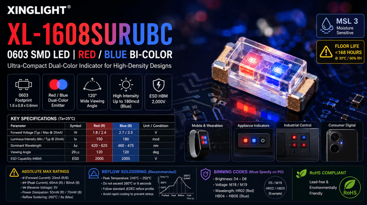
The XL-1608SURUBC is an ultra-compact 0603 (1608 metric) SMD LED designed by XINGLIGHT, featuring a dual-color Red/Blue emitter in a transparent water-clear package. It is specifically engineered for high-density signal indication and status display applications where PCB real estate is at a premium. For design engineers, the critical selection variables are the low forward voltage (Vf) window to match driving ICs and the tight wavelength binning required for consistent color uniformity in mass production.
🎯 Typical Applications & Design Context
Based on its 1.6mm x 0.8mm footprint and wide 120° viewing angle, this component is ideally suited for space-constrained consumer electronics.
- Mobile & Wearables: Indicator lights and backlighting for buttons/keypads due to low power consumption.
- Status Indication: Pilot lamps for appliances or industrial control panels (PCB mounted).
- Consumer Digital: Mobile phone auxiliary displays or camera flash indicators.
💡 Design Fit: The transparent colloid ensures high luminous intensity, but designers must account for potential light mixing (magenta/purple) if both Red and Blue are activated simultaneously without physical diffusion barriers.
📊 Key Technical Specifications
💡 Performance Window (Ta=25°C)
| Parameter | Symbol | Red (R) Value | Blue (B) Value | Unit | Notes |
|---|---|---|---|---|---|
| Forward Voltage | Vf | 1.8 / 2.4 | 2.7 / 3.3 | V | Typ / Max @ 20mA |
| Luminous Intensity | Iv | 150 | 180 | mcd | Min Typ @ 20mA |
| Dominant Wavelength | λd | 620-625 | 460-475 | nm | Critical for color binning |
| Viewing Angle | 2θ1/2 | 120 | 120 | deg | Wide angle for indicators |
| ESD Capability | ESD | 2000 | 2000 | V | Human Body Model (HBM) |
⚠️ Absolute Maximum Ratings & Process Limits
Exceeding these parameters risks immediate catastrophic failure or latent reliability issues.
👇 Critical Process Boundaries
| Parameter | Rating (Red) | Rating (Blue) | Unit | Failure Consequence |
|---|---|---|---|---|
| Forward Current | 20 | 20 | mA | Bond wire lift-off or junction degradation. |
| Peak Current | 60 | 80 | mA | Thermal runaway if duty cycle exceeds 10% (≤0.1ms pulse). |
| Reverse Voltage | 5 | 5 | V | Avalanche breakdown causing permanent leakage. |
| Power Dissipation | 50 | 70 | mW | Overheating leading to epoxy yellowing or delamination. |
| Soldering (Reflow) | 260°C / 6s | - | °C / s | Exceeding 260°C or time may crack the epoxy lens or de-solder the leadframe. |
⚠️ E-E-A-T Insight: The 260°C rating is the absolute maximum. In practice, ensure your Reflow Profile peak stays between 245°C-250°C to preserve the transparent colloid clarity and adhesive strength.
🧩 Package, Dimensions & Assembly Notes
- Package Type: 1608 Metric (Imperial 0603).
- Dimensions: 1.6mm (L) x 0.8mm (W) x 0.6mm (H).
- MSL (Moisture Sensitivity):Level 3.
- ⚠️ Action Required: Floor life is < 168 hours at 30°C/60% RH. If exposed longer, baking is mandatory (Ref: JEITA ED-4701 / 300.301) to prevent "popcorning" during reflow.
- Soldering: Compatible with standard SMT automation. Land pattern design should follow EIA standards for 0603 components to ensure tombstoning does not occur due to thermal imbalance.
🔍 Procurement & Sourcing Insights
- Binning & Consistency: The datasheet lists strict codes for Brightness (D4-D8), Voltage (M18/M19), and Wavelength (HR02/HB04-06). Procurement must specify these codes on the PO. Blind sourcing without bin codes leads to visible color inconsistency on the final production panel.
- Supply Chain: XINGLIGHT is a standard domestic (China) manufacturer. While global availability is generally good, lead times can fluctuate.
- Alternative Strategy: When validating alternatives, match the Vf group and Wavelength bin precisely.
🚀 LDeepAI Recommendation: We recommend securing a "Golden Sample" of the specific bin code required for your project to enable First Article Inspection (FAI) on every batch.
❓ FAQ
Q: What is the difference between Dominant Wavelength and Peak Wavelength for this part?
A: Dominant Wavelength (e.g., 620-625nm for Red) defines the perceived color by the human eye and is critical for color matching. Peak Wavelength (e.g., 630nm) is the physical maximum emission intensity on the spectrum. For procurement, focus on controlling the Dominant Wavelength tolerance.
Q: The datasheet mentions MSL Level 3. Do I need to bake this before assembly?
A: Only if the dry packaging has been open for more than 168 hours (1 week). If the vacuum-seal is broken and the components sit in the factory environment for > 1 week, bake at 125°C for 24 hours (standard for Level 3) to prevent moisture-induced cracking during reflow.
Q: Can I drive the Red and Blue chips simultaneously?
A: Yes, but be aware of the voltage difference. Red Vf is ~2.0V, while Blue Vf is ~3.0V. If using a single resistor for both in parallel, the Blue may dim or the Red may overcurrent depending on the supply voltage. Separate control channels are recommended for mixed-color applications.
Q: How does the brightness binning (D4, D5...) affect my BOM?
A: The brightness (IV) ranges from 150mcd to 300mcd. A "D4" bin (150-180mcd) is visibly dimmer than a "D8" (270-300mcd). Mixing these bins on the same production line will result in uneven indicator brightness. Your BOM should lock down one specific bin code (e.g., D5) for mass production.