📌 Product Overview
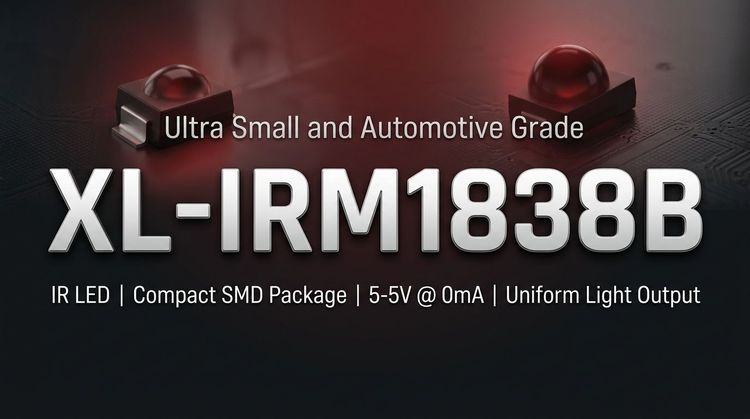
The XL-IRM1838B from XINGLIGHT is a miniaturized infrared receiver module designed for infrared remote control systems. It integrates a high-speed, high-sensitivity PIN photodiode and a low-power, high-gain preamplifier IC into a single epoxy resin package. This component functions as the receiver front-end, converting optical signals into electrical TTL/CMOS compatible outputs.
👇 Design focus is placed on its dual shielding architecture, which utilizes both internal and external EMI suppression to ensure stability in electrically noisy environments. With a compact footprint of 7.6mm x 5.1mm, it is ideal for space-constrained PCBs in consumer appliances and industrial equipment.
💡 Typical Applications
- Consumer Appliances: Air conditioners, fans, heaters, and humidifiers requiring reliable remote control decoding.
- Multimedia & AV: Integration into televisions, DVD players, set-top boxes, and vehicle-mounted mobile DVD systems.
- Industrial & Computing: Usage in instrumentation, industrial automation controls, computer peripherals, and induction sanitaryware.
- Automotive & Lighting: Suitable for automotive electronics and lighting systems where long-distance reception and wide voltage tolerance are critical.
⚙️ Key Technical Specifications
📊 The following table outlines the electro-optical characteristics under standard test conditions (Ta=25°C, VDD=5V):
| Parameter | Symbol | Min. | Typ. | Max. | Unit | Test Condition |
|---|---|---|---|---|---|---|
| Supply Voltage | VDD | 2.7 | - | 5.5 | V | Recommended Range |
| Carrier Frequency | f₀ | - | 37.9 | - | kHz | Center Frequency |
| BPF Width | fBW | - | 6 | - | kHz | Bandwidth |
| Working Current | ICC | 0.3 | - | 0.5 | mA | VDD=5V |
| Reception Distance | L | 10 | 15 | - | m | 0° (Test CH3018-12U) |
| Reception Angle | L | 5 | 6 | - | m | Left/Right 35° |
| Low Level Output | Vol | - | - | 250 | mV | Isink=2.0mA |
| High Level Output | Voh | 4.5 | - | 5.0 | V | VCC=5V |
⚠️ Absolute Maximum Ratings & Process Limits
🔒 Exceeding these ratings may cause permanent damage to the device. Stress beyond these limits for extended periods affects reliability.
| Parameter | Symbol | Rating | Unit | Notes |
|---|---|---|---|---|
| Supply Voltage | VDD | 6.0 | V | Maximum operating input |
| Operating Temp | Topr | -20 ~ +85 | °C | Ambient range |
| Storage Temp | Tstg | -40 ~ +125 | °C | Non-operating range |
| Soldering (Wave) | Tsol | 240 | °C | ≤6 seconds duration |
| Soldering (Manual) | Tsol | 300 | °C | ≤3 seconds duration |
⚠️ Critical Note: The low-level output voltage is guaranteed up to 2.0mA sink current. Designs must ensure the signal load does not exceed this current limit to maintain logic compatibility.
📦 Package, Dimensions & Assembly Notes
- Package Type: Large volume epoxy plastic nose-bridge type with semi-circular spherical packaging.
- Dimensions: 7.6mm (L) x 5.1mm (W) x 3.5mm (H).
- Pin Length: 22.0mm (standard), designed for Through-Hole Technology (THT).
- Shielding: Features internal and external dual shielding to resist environmental light interference.
- Assembly: Compatible with standard wave soldering (240°C, ≤6s) and manual soldering processes. Ensure the IR receiver window is not obstructed by the chassis or PCB components to maintain the specified reception angle.
🚀 Sourcing & Supply Considerations
- Environmental Compliance: 🟢 Certified by REACH and ROHS, ensuring suitability for export to markets with strict environmental regulations.
- Supply Chain: Widely used in financial electronics and office machines; availability is generally stable, but verify lead times for high-volume industrial batches.
- Quality Control: Verify the "XINGLIGHT" branding and packaging to avoid counterfeit components which may have lower sensitivity or reduced EMI shielding.
- Technical Support: For mass production testing or cross-replacement inquiries, direct consultation is recommended.
❓ FAQ
Q: What is the carrier frequency tolerance for the XL-IRM1838B?
A: The typical center carrier frequency is 37.9 kHz with a Band Pass Filter (BPF) width of 6 kHz. It is optimized for standard remote control protocols.
Q: Can this component operate directly from a 3.3V microcontroller rail?
A: Yes. The recommended operating voltage range is 2.7V to 5.5V, making it fully compatible with 3.3V logic systems without needing an external regulator.
Q: What is the typical reception distance in a real-world environment?
A: Under standard test conditions (no direct sunlight, specific lux interference), the reception distance is typically 10-15 meters at 0 degrees. At 35-degree angles, this reduces to approximately 5-6 meters.
Q: Does the metal shielding require grounding during assembly?
A: The datasheet describes a "dual shielding" design for anti-interference. Standard assembly practice usually involves ensuring the metal shield is properly connected to the ground plane (often via the PCB ground pad) to maximize EMI immunity.
Q: How should I handle the soldering process to avoid damage?
A: For wave soldering, temperatures should not exceed 240°C for longer than 6 seconds. For manual welding, do not exceed 300°C for more than 3 seconds.
Q: Is the output active high or active low?
A: The output is Low Level Effective (Active Low). The output pin pulls low when a valid infrared signal is detected and returns to a high level when idle or no signal is present.