📌 Product Overview
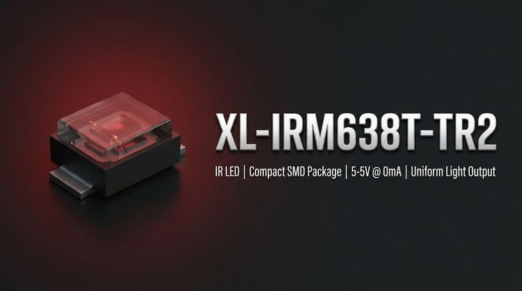
The XL-IRM638T-TR2 is a miniature, epoxy-encapsulated infrared receiver module designed for surface mount technology (SMT) assembly. It integrates a high-speed PIN photodiode and a low-power preamplifier IC into a compact 5.0 x 4.0 x 4.0mm package, specifically engineered to minimize footprint in dense circuit layouts. With a built-in bandpass filter tuned to 37.9 kHz and dual internal shielding, the component effectively suppresses environmental electrical noise, ensuring signal integrity in complex household or industrial settings.
⚙️ Typical Applications
The XL-IRM638T-TR2 is primarily utilized in consumer electronics and industrial control systems requiring reliable remote command execution:
- Consumer Appliances: Air conditioners, fans, heaters, and humidifiers where compact form factors are essential.
- Multimedia Systems: Televisions, DVD players, set-top boxes, and vehicle-mounted infotainment displays.
- Industrial & Automation: Instrumentation panels, sensing equipment, and industrial automation controllers.
- Peripheral Devices: Computer accessories, lighting controls, and induction sanitary ware requiring non-contact activation.
📊 Key Technical Specifications
The electrical performance of the XL-IRM638T-TR2 is optimized for low-voltage operation and long-distance signal acquisition, as detailed in the table below:
| Parameter | Symbol | Test Conditions | Min. | Typ. | Max. | Unit |
|---|---|---|---|---|---|---|
| Supply Voltage | VDD | Recommended Usage | 2.7 | - | 5.5 | V |
| Carrier Frequency | $f_0$ | - | - | 37.9 | - | kHz |
| BPF Width | $f_{BW}$ | - | - | 6 | - | kHz |
| Working Current | $I_{CC}$ | $V_{DD}=5V$ | 0.4 | 0.5 | 0.7 | mA |
| Reception Distance | L | $0^\circ$ Angle | 15 | 20 | - | m |
| Low Level Output | $V_{OL}$ | $I_{sink}=2.0mA$ | - | - | 250 | mV |
| High Level Output | $V_{OH}$ | $V_{CC}=5V$ | 4.5 | - | 5.0 | V |
⚠️ Absolute Maximum Ratings & Process Limits
Engineers must strictly adhere to the following stress limits to prevent permanent damage to the integrated circuit and photodiode. Exceeding these values during assembly or operation compromises reliability.
| Parameter | Symbol | Rating | Unit | Notes |
|---|---|---|---|---|
| Supply Voltage | $V_{DD}$ | 6.0 | V | Do not exceed continuous supply |
| Operating Temp. | $T_{opr}$ | -20 to +85 | $^\circ$C | Ambient range for stable function |
| Storage Temp. | $T_{stg}$ | -40 to +125 | $^\circ$C | Long-term non-operating storage |
| Soldering (Wave) | $T_{sol}$ | 260 | $^\circ$C | $\le$ 6 seconds duration |
| Soldering (Manual) | $T_{sol}$ | 300 | $^\circ$C | $\le$ 3 seconds duration |
🏗️ Package, Dimensions & Assembly Notes
The XL-IRM638T-TR2 utilizes an epoxy resin plastic encapsulation with a semi-circular dome design. This structure optimizes the incident angle for incoming IR signals while maintaining mechanical durability.
- Dimensions: 5.0mm (Length) x 4.0mm (Width) x 4.0mm (Height).
- Shielding: Features dual shielding (internal and external) to resist electrical interference from power lines or fluorescent lighting.
- Soldering: The component is compatible with standard wave soldering and manual rework. Ensure temperature profiles do not exceed the maximum ratings to avoid degrading the epoxy or internal bonds.
🚚 Sourcing & Supply Considerations
- Environmental Compliance: Verified ROHS and REACH certification ensures suitability for global markets, including the EU.
- Signal Stability: Built-in immunity against 200±50 Lux fluorescent light interference reduces failure rates in field deployments.
- Voltage Range: Wide 2.7V–5.5V input tolerance simplifies BOM management by supporting both 3.3V and 5V logic designs.
❓ FAQ
Q: What is the carrier frequency tolerance for this receiver?
A: The typical carrier frequency ($f_0$) is 37.9 kHz with a Bandpass Filter (BPF) width of 6 kHz, ensuring compatibility with standard transmission protocols.
Q: Can the XL-IRM638T-TR2 operate at 3.3V logic levels?
A: Yes. The recommended supply voltage range is 2.7V to 5.5V, making it suitable for both 3.3V and 5.V systems. It supports TTL and CMOS interface levels.
Q: What is the maximum operating temperature?
A: The component can operate reliably in ambient temperatures ranging from -20°C to +85°C, covering standard indoor industrial and residential environments.
Q: What are the reflow soldering limits?
A: For wave soldering, the limit is 260°C for $\le$ 6 seconds. For manual welding, the limit is 300°C for $\le$ 3 seconds to prevent thermal damage.
Q: Does the datasheet specify a specific transmission distance?
A: Yes. Under standard test conditions ($V_{DD}=5V$), the reception distance ($L$) is typically 20m at $0^\circ$ and 5m at $\pm35^\circ$.