📌 Product Overview
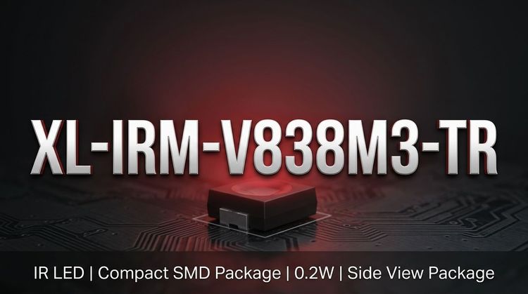
The XL-IRM-V838M3-TR is a miniature, epoxy-encapsulated infrared receiver designed for SMT assembly. 💡 It integrates a high-sensitivity PIN photodiode and a low-power preamplifier IC into a compact 6.8 x 3.0 mm shielded package.
This component is specifically engineered for infrared remote control systems requiring high immunity against environmental light and electrical interference. 👇 Its design focus is providing stable TTL/CMOS low-active output for consumer electronics and industrial interfaces.
🎯 Typical Applications
This module is optimized for short-to-medium range wireless control in environments with moderate ambient light interference. Key deployment scenarios include:
- Consumer Appliances: Air conditioners, fans, humidifiers, and heaters.
- Multimedia Systems: Set-top boxes, DVD players, and vehicular infotainment screens.
- Industrial & Computing: Instrumentation panels, induction sanitaryware, and PC peripherals.
📊 Key Technical Specifications
💡 Performance is centered on a 37.9 kHz carrier frequency with robust reception angles. The following table outlines standard electrical characteristics ($T_a = 25^\circ C$).
| Parameter | Symbol | Min | Typical | Max | Unit | Test Conditions |
|---|---|---|---|---|---|---|
| Supply Voltage | $V_{CC}$ | 2.7 | - | 5.5 | V | - |
| Supply Current | $I_{CC}$ | - | 0.22 | 0.6 | mA | $V_{CC}=5.0V$ |
| Reception Distance | $L$ ($0^\circ$) | - | 40 | - | m | Standard test |
| Reception Distance | $L$ ($\pm45^\circ$) | - | 25 | - | m | Standard test |
| Peak Wavelength | $\lambda_P$ | - | 940 | - | nm | - |
| Half Angle | $2\theta_{1/2}$ | - | 45 | - | Deg | - |
| Low Level Output | $V_{OL}$ | - | - | 0.4 | V | - |
⚠️ Absolute Maximum Ratings & Process Limits
Exceeding these limits may cause permanent damage to the device. 👇 These parameters are critical for establishing safety margins in power supply design and storage environments.
| Parameter | Symbol | Rating | Unit | Notes |
|---|---|---|---|---|
| Supply Voltage | $V_{CC}$ | -0.2 ~ +6.0 | V | Functional range is 2.7-5.5V |
| Operating Temp. | $T_{opr}$ | -20 ~ +85 | $^\circ$C | Ambient operating range |
| Storage Temp. | $T_{stg}$ | -40 ~ +125 | $^\circ$C | - |
| Reflow Soldering | $T_{sol}$ | 260 | $^\circ$C | Max 6 seconds duration |
| Manual Welding | $T_{sol}$ | 300 | $^\circ$C | Max 3 seconds duration |
📦 Package, Dimensions & Assembly Notes
- Package Type: Epoxy resin plastic encapsulated, semi-circular spherical top view.
- Dimensions: 6.8mm (L) $\times$ 3.0mm (W) $\times$ 3.2mm (H).
- Design Features: Internal and external dual shielding significantly reduces EMI.
- Soldering: Designed for standard Reflow soldering profiles (peak 260°C).
- ESD Protection: 💡 Datasheet schematics suggest external filtering is recommended to stabilize the supply voltage against switching noise.
🚀 Sourcing & Supply Considerations
- Compliance: 🌱 Certified RoHS and REACH compliant for environmental safety.
- Packaging: Supplied in Tape & Reel (TR) format for automated placement.
- Yield Risks: Verify shielding integrity during incoming inspection to ensure consistent performance in high-interference environments.
- Authenticity: Source from authorized channels to guarantee specifications for carrier frequency tolerance and distance reception.
❓ FAQ
Q: What is the carrier frequency tolerance for this IR receiver?
A: The XL-IRM-V838M3-TR is optimized for a typical carrier frequency of 37.9 kHz. It is designed to handle standard data formats with a minimum burst length of 300 µs and a minimum gap time of 300 µs between bursts.
Q: Can this module be used directly with a 3.3V MCU?
A: Yes. The supply voltage range is 2.7V to 5.5V, making it compatible with both 3.3V and 5.0V logic systems. The output is TTL and CMOS compatible with a low-active effective level.
Q: What are the critical assembly constraints to prevent damage?
A: The maximum soldering temperature must not exceed 260°C for more than 6 seconds during reflow. For manual welding, the limit is 300°C for 3 seconds. Adhering to these thermal limits prevents internal IC damage.
Q: How does the dual-shielding design benefit the application?
A: The internal and external dual shielding minimizes susceptibility to electromagnetic interference (EMI) and environmental light noise. This ensures reliable reception distances (up to 40m) even in electrically noisy environments like appliances or automotive cabins.