
Specifications
| Type | Description |
|---|---|
| Part Number | XL-IRM1738C |
| Manufacturer | XINGLIGHT |
| Product Type | SMD LED |
| Category | LED |
| Package / Case | SMD epoxy resin semi-spherical package, 6.8 x 5.3 x 4.4 mm body, 3.1 mm pin length |
| Supply Voltage Absolute Maximum | 6.0 V; Ta=25°C |
| Operating Ambient Temperature | -40°C to +85°C; absolute maximum rating |
| Storage Ambient Temperature | -40°C to +125°C; absolute maximum rating |
| Lead Soldering Temperature and Time | 260°C, <=6 s; absolute maximum rating |
| Working Current | 0.2 mA min, 0.3 mA typ, 0.5 mA max; VDD=5 V, Ta=25°C |
| Receive Distance at 0 Degrees | 10 m min, 12 m typ; CH3018-12U emitter, indoor without direct sunlight on receiver window, 40 W electronic ballast fluorescent lamp 1 m front-above, 200±50 lux |
| Receive Distance at Left 35 Degrees | 5 m min, 6 m typ; CH3018-12U emitter, indoor without direct sunlight on receiver window, 40 W electronic ballast fluorescent lamp 1 m front-above, 200±50 lux |
| Receive Distance at Right 35 Degrees | 5 m min, 6 m typ; CH3018-12U emitter, indoor without direct sunlight on receiver window, 40 W electronic ballast fluorescent lamp 1 m front-above, 200±50 lux |
| Carrier Frequency | 37.9 kHz typ; Ta=25°C |
| BPF Width | 6 kHz typ; Ta=25°C |
| Low Level Output Voltage | 250 mV max; Isink=2.0 mA |
| High Level Output Voltage | 4.5 V min, 5.0 V max; VCC=5 V |
| Output Pulse Width Low | 400 us min, 600 us typ, 800 us max; burst wave, Vin=500 uVp-p |
| Output Pulse Width High | 400 us min, 640 us typ, 800 us max; burst wave, Vin=50 mVp-p |
| Minimum Pulse Width | 350 us min; Vin=50 mVp-p |
| Minimum Interval Time | 450 us min; Vin=50 mVp-p |
| Encoding Pause Time | 45 us min; Vin=50 mVp-p |
| Recommended Supply Voltage | 2.7 V min, 5.5 V max; recommended usage condition |
| Recommended Input Frequency | 37.9 kHz typ; recommended usage condition |
| Recommended Operating Temperature | 25°C typ; recommended usage condition |
| Moisture Sensitivity Level | MSL 3; product characteristic |
| Output Logic Compatibility | TTL and CMOS compatible, active low; product characteristic |
| Solder Heat Reliability Test | 260°C±5°C, within 5 s, 20 tested, 20 passed; non-stress state |
| ESD Reliability Test | 4 kV, 100 pF capacitor, 1.5 kOhm resistor, each pin, 20 tested, 20 passed; electrostatic destruction test |
| Vibration Reliability Test | 10-50 Hz/1 min, 1.5 mm amplitude, X/Y/Z for 30 min, 20 tested, 20 passed; vibration test |
| High Temperature Storage Test | 85°C±2°C for 240 h, 20 tested, 20 passed; reliability test |
| Low Temperature Storage Test | -20°C±2°C for 240 h, 20 tested, 20 passed; reliability test |
| High Temperature High Humidity Storage Test | 85°C, 85% RH for 240 h, 20 tested, 20 passed; reliability test |
| Temperature Cycle Test | -20°C for 30 s and +85°C for 30 s, 10 cycles, 20 tested, 20 passed; high-low temperature cycle |
| Pin Bending Test | 2.5 N external force, each pin bent 2 times, 20 tested, 20 passed; reliability test |
| Outline Dimension Tolerance | ±0.25 mm; unless otherwise specified |
| Carrier Tape Dimension Tolerance | ±0.1 mm; packaging dimensions |
| Manual Soldering Iron Power | <30 W recommended; hand soldering for repair/rework |
| Manual Soldering Temperature | <300°C; hand soldering |
| Manual Soldering Time | <3 s per terminal, one time only; hand soldering |
| Recommended Maximum Reflow Temperature | 240°C for 6 s; Pb-free reflow soldering |
| Maximum Reflow Count | 2 times; reflow soldering |
| Datasheet Status | request_only |
Product Overview
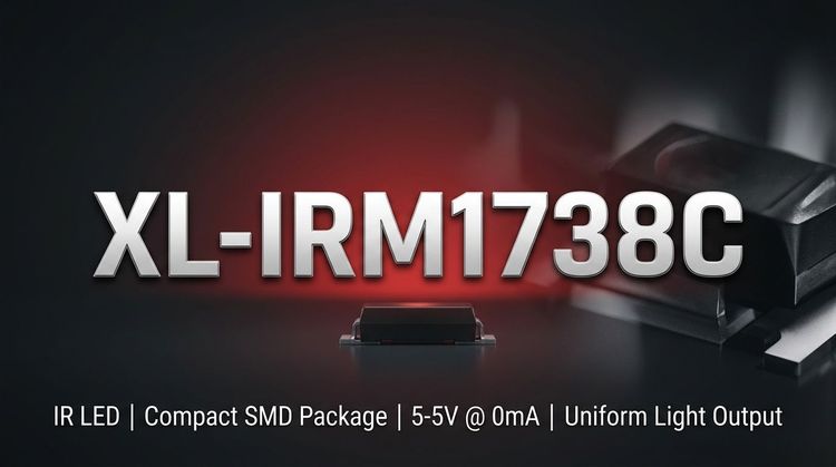
The XL-IRM1738C is a XINGLIGHT infrared remote receiver module listed in the LED category. It is supplied in an SMD epoxy resin semi-spherical package with a 6.8 x 5.3 x 4.4 mm body and 3.1 mm pin length, with outline dimensions specified to ±0.25 mm unless otherwise noted.
Electrical data includes a recommended supply range of 2.7 V to 5.5 V, a 37.9 kHz typical input/carrier frequency, and 0.2 mA minimum, 0.3 mA typical, 0.5 mA maximum working current at VDD=5 V and Ta=25°C. Output is TTL and CMOS compatible with active-low logic, including a 250 mV maximum low-level output at Isink=2.0 mA.
Receive-distance data is specified with a CH3018-12U emitter under indoor lighting conditions: 10 m minimum and 12 m typical at 0 degrees, and 5 m minimum and 6 m typical at left or right 35 degrees. Assembly data includes MSL 3, manual soldering below 300°C for less than 3 seconds per terminal, and Pb-free reflow up to 240°C for 6 seconds, with a maximum of two reflow cycles.
Key Features
- Infrared remote receiver module in SMD epoxy resin package
- 6.8 x 5.3 x 4.4 mm body dimensions
- Recommended 2.7 V to 5.5 V supply range
- 37.9 kHz typical carrier and input frequency
- TTL and CMOS compatible active-low output logic
- 0.3 mA typical working current at 5 V
- 12 m typical receive distance at 0 degrees
- 6 m typical receive distance at left or right 35 degrees
- MSL 3 moisture sensitivity level specified
- Pb-free reflow profile supports 240°C for 6 seconds
Typical Applications
- Infrared remote control receivers
- Consumer electronics remote input
- Home appliance control interfaces
- TTL logic IR receiver inputs
- CMOS logic IR receiver inputs
- Surface-mount control boards
- 37.9 kHz carrier remote systems
Procurement Notes
When requesting a quote for XL-IRM1738C, buyers should confirm the manufacturer, package or case, required quantity, target date code, compliance documents, packing method, destination country and expected delivery schedule.
If alternatives are acceptable, buyers should share the approved vendor list, required electrical or optical limits, package constraints and qualification requirements. Any alternative part should be reviewed by the buyer's engineering team before production use.
For LED and optoelectronic sourcing, brightness bin, wavelength or color temperature bin, forward voltage range, viewing angle, moisture sensitivity level and soldering process limits may affect final selection, availability and lead time.
Related Technical Articles
FAQ
What is the recommended supply range for XL-IRM1738C?
The recommended supply voltage for XL-IRM1738C is 2.7 V minimum to 5.5 V maximum. The absolute maximum supply voltage is listed separately as 6.0 V at Ta=25°C.
What carrier frequency does XL-IRM1738C use?
XL-IRM1738C is specified with a 37.9 kHz typical carrier frequency at Ta=25°C. The recommended input frequency is also listed as 37.9 kHz typical under recommended usage conditions.
What output logic is provided by this receiver module?
The module output is TTL and CMOS compatible and active low. Electrical output data includes 250 mV maximum low-level output voltage at Isink=2.0 mA and 4.5 V minimum to 5.0 V maximum high-level output voltage at VCC=5 V.
What soldering limits are specified for XL-IRM1738C?
Hand soldering is specified below 300°C for less than 3 seconds per terminal, one time only, with less than 30 W soldering iron power recommended for repair or rework. Pb-free reflow is specified up to 240°C for 6 seconds, maximum two times.
Technical Review & Sourcing Note
Prepared by LDeepAI Component Sourcing Team. Reviewed for RFQ, documentation and alternative sourcing use. Last updated: June 30, 2026.
This page is based on manufacturer datasheet information and LDeepAI sourcing review. Specifications should be verified against the official manufacturer datasheet before final procurement or design approval. Final electrical, optical and reliability approval should be confirmed by the buyer's engineering team.