📌 Product Overview
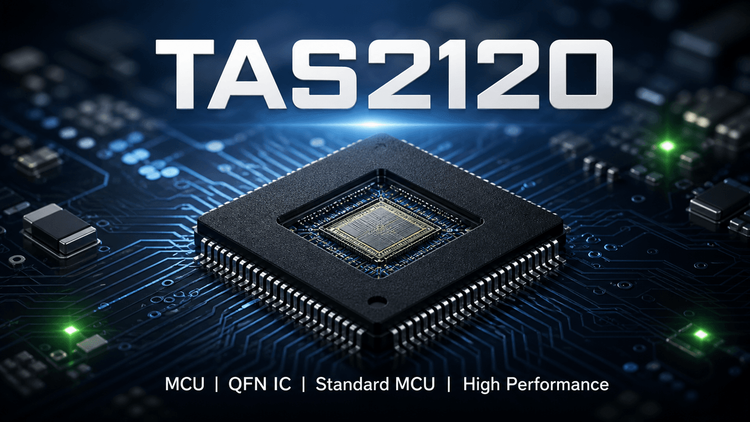
The TAS2120 is a mono, digital-input Class-D speaker amplifier featuring an integrated 14.75V Class-H boost converter. Designed by Texas Instruments, this component is specifically engineered to maximize battery life in portable systems while delivering high-fidelity audio output.
💡 Why this matters: Unlike traditional amplifiers requiring a fixed high-voltage rail, the TAS2120 dynamically adjusts the boost voltage to match the audio signal's envelope. For OEMs designing smart speakers, Bluetooth speakers, or wearables, this device eliminates the need for a separate boost IC and significantly reduces idle power consumption, making it ideal for battery-operated consumer electronics.
🎯 Typical Applications & Design Context
The TAS2120 is optimized for applications where space constraints and power efficiency are critical.
- Smart Speakers & Voice Assistants: The low idle channel power (5.3mW with noise gate on) ensures the device remains ready for voice triggers without draining the battery.
- Bluetooth & Wireless Audio: The integrated boost (up to 5.1A current limit) supports loud peak volumes without dropout, essential for portable Bluetooth speakers.
- Wearables & Tablets: The high efficiency (up to 91% @ 1W) minimizes heat generation in compact, thermally constrained form factors like smartwatches or slim tablets.
📊 Key Technical Specifications
| Parameter | Specification | Engineering Note |
|---|---|---|
| Output Power | 8.2W @ 1% THD+N | Delivers sufficient headroom for peak transients in small enclosures. |
| Boost Voltage | 14.75V (Integrated Class-H) | Dynamic voltage tracking minimizes power loss compared to fixed rail amps. |
| Efficiency | Up to 91% @ 1W (8Ω) | Critical for thermal management in plastic housings. |
| Idle Power | 5.3mW (Noise Gate On) | Extends standby time for "always-listening" devices. |
| Signal Interface | I2S/TDM (up to 8 ch) & I2C | Supports high sample rates (16-192kHz) and direct digital input. |
| Logic Levels | IOVDD: 1.8V or 3.3V | Flexible interface compatibility with various host processors. |
⚠️ Absolute Maximum Ratings & Process Limits
| Parameter | Rating | Failure Mechanism (E-E-A-T Insight) |
|---|---|---|
| VBAT (Supply) | -0.3V to 5.5V | Exceeding 5.5V risks permanent damage to the input MOSFETs; strict input protection is required during USB fast-charge transients. |
| PVDD (Boost Output) | -0.3V to 17V | Overvoltage here can destroy the Class-D output FETs. Ensure feedback loops are stable during load transients. |
| Junction Temp (Tj) | -40°C to 150°C | Exceeding 150°C triggers thermal shutdown, cutting off audio unexpectedly. In plastic enclosures, poor layout can push Tj to this limit at high volume. |
| ESD Rating | HBM 2kV, CDM 500V | Standard handling precautions required. High-voltage static discharge during assembly or end-user handling can cause latent defects. |
🧩 Package, Dimensions & Assembly Notes
- Package Type:26-Pin QFN (4mm × 3.5mm).
- Pitch: 0.4mm (Fine pitch).
- Thermal Pad: The central thermal pad (on the bottom) must be soldered to the PCB ground plane for heat dissipation. Multiple vias are required under the pad to conduct heat to inner or backside layers.
- SMT Process: This is a moisture-sensitive device. Reflow profiling must adhere to IPC/JEDEC J-STD-020 for moisture sensitivity.
- Layout Sensitivity: The SW (switch) node and BGND (boost ground) pins must connect to the PCB GND plane with multiple vias immediately adjacent to the pin to minimize noise and inductance.
🔍 Procurement & Sourcing Insights
- Supply Status: As a TI device, general availability is usually stable through franchised distributors, but lead times for specific QFN variants can fluctuate with consumer demand cycles.
- BOM Risk: The 0.4mm pitch is a standard footprint, but tight layout control makes last-second substitution difficult. Substituting with a non-TI analog requires a complete PCB layout spin due to different pinouts and boost architecture.
- Sourcing Strategy: Be wary of " remarked" or "scrubbed" components in open markets. Verify the date code and origin traceability to avoid counterfeit parts that may fail under the high-current switching conditions of the integrated boost.
- Alternative: Direct pin-to-pin replacements are rare. Engineering re-validation is mandatory if switching to an alternative Class-D amp with integrated boost.
❓ FAQ
Q1: Can I use a fixed 12V supply instead of the internal boost?
A: Yes, the datasheet supports an External PVDD supply mode. However, you lose the efficiency benefits of the Class-H tracking algorithm. You must configure the device correctly via I2C or hardware pins to disable the internal boost converter.
Q2: Why is the 0.4mm pitch a procurement concern?
A: While 0.4mm is common, it leaves little room for PCB etching tolerance. If manufacturing tolerances drift during PCB fabrication, bridging risks increase. Procurement should ensure the PCB fab shop is capable of 0.1mm / 4mil trace/space to guarantee yield.
Q3: What is the risk of "Thermal Shutdown" in a plastic speaker enclosure?
A: The TAS2120 relies on the PCB for cooling. If the design lacks sufficient copper area or internal layers for heatsinking, the junction temperature (Tj) will rise rapidly during high-volume playback, triggering the protection circuit and causing sudden silence. This is a common failure mode in compact wearables.
Q4: Is the "Clock Free" operation suitable for low-power standby?
A: Yes, the "MCLK free operation" feature allows the device to operate without a continuous master clock, saving power in system idle modes. However, synchronization latency must be managed when the system wakes up.