📌 Product Overview
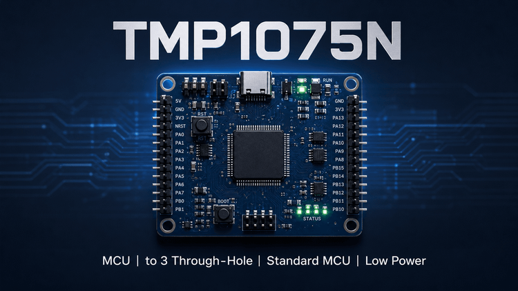
The Texas Instruments TMP1075N is a high-precision digital temperature sensor designed for low-power, space-constrained electronic systems. Targeting engineering applications requiring NIST-traceable accuracy without the complexity of analog thermistor circuitry, this device serves as a critical component for thermal management in SSDs, server motherboards, and industrial PLCs. 💡
Unlike standard logic ICs, the TMP1075N prioritizes Voltage Linearity and Power Supply Rejection (PSR) over raw speed. For procurement and R&D teams, the critical selection variable is the "1.62V minimum supply voltage" requirement, which distinguishes it from broad-range competitors like the TMP112. It is specifically optimized to replace NTC thermistors in high-density boards where real estate and power budget are strictly constrained.
🎯 Typical Applications & Design Context
- Data Center & Enterprise Computing: Used in Solid State Drives (SSD) and Rack Server Motherboards for real-time thermal throttling, leveraging the 1.62V to 3.6V range to match core logic voltages directly.
- Industrial Automation (Factory Control): Deployed in Machine Vision Cameras and Single Board Computers (SBC) where environmental operating temperatures range from -40°C to +125°C.
- Building Automation & HVAC: Suitable for wireless environmental sensors due to ultra-low active current (4.8μA @ 4Hz) and shutdown mode (0.15μA), extending battery life in remote IoT nodes.
- Consumer Electronics: Integrated into smart speakers and AR glasses; the SOT563 (1.6mm × 1.6mm) package fits onto crowded PC boards where larger sensors are impossible.
📊 Key Technical Specifications
| Parameter | Value/Condition | Significance |
|---|---|---|
| Accuracy (Grade) | ±1°C (Max) from -40°C to +125°C | ✅ Guarantees reliability without calibration across full industrial temp range. |
| Supply Voltage | 1.62V to 3.6V | ⚠️ Critical Design Limit: Narrower than TMP112 (1.4V); ensure VDD stability in brown-out conditions. |
| Interface | I2C / SMBus (Two-Wire) | Standard logic control; allows up to 4 devices per bus. |
| Resolution | 12-bit (0.0625°C) | Enables precise detection of minor thermal drifts in high-performance CPUs. |
| Conversion Time | 10ms (Typical) | Adequate for thermal loop monitoring (does not require high-speed polling). |
| Quiescent Current | 4.8μA @ 4Hz (Active) | Low power consumption minimizes impact on battery-powered devices. |
⚠️ Absolute Maximum Ratings & Process Limits
| Parameter | Rating | E-E-A-T Engineering Insight |
|---|---|---|
| Supply Voltage (V+) | -0.3V to +4.0V | Exceeding 4.0V risks immediate gate oxide breakdown. 🔒 If the local 3.3V rail has spikes >4.0V (e.g., inductive kickback), add clamping protection. |
| Input Current (Any Pin) | ±10mA | Current limiting is required on SDA/SCL lines if bus voltage differs from sensor VDD. |
| Operating Temp (Junction) | -55°C to +150°C | While the sensor measures -40 to 125, the silicon itself withstands higher thermal stress during SMT reflow. |
| Lead Temp (Soldering) | 260°C (for 10s-60s) | SMT Validation: Do not exceed this profile. Pb-free reflow typically peaks at 245°C; ensure conveyor speed is calibrated to prevent thermal shock. |
🧩 Package, Dimensions & Assembly Notes
- Package Type: SOT563 (6-pin)
- Dimensions: 1.6mm × 1.6mm × 0.6mm (Body)
- Footprint: 68% smaller than standard SOT23.
- SMT Challenge: Due to the ultra-small form factor, wetting balance is critical. Ensure stencil apertures are designed for ~50% area reduction to prevent solder bridging on pins 1 and 6 (V+ and GND).
- Thermal Path: The primary thermal conduction path is through the PCB lands. Avoid placing this sensor under "dead air" or high-impedance RF shields; it must "feel" the ambient air or the target component surface to function accurately.
🔍 Procurement & Sourcing Insights
- Supply Chain Volatility: 🚨 As of 2024, TI's sensor allocation in specific 1.6mm packages can fluctuate. Lead times may extend to 12-20 weeks for high mix configs.
- Alternative Risks: Many sensors claim "TMP112 compatible" but ignore the 1.62V minimum VDD of the TMP1075N. Swapping in a generic 1.4V part without checking firmware scaling can cause a "floating rail" read error below 1.62V.
- Counterfeit Detection: Verify the laser-mark part date code (YWW) against TI's traceability database.
- Sourcing Strategy: For EMS teams, suggest authorizing a pin-to-pin alternative (like NCP18WF or generic Silicon Labs sensors) only if the firmware supports the "One-Shot" conversion timing differences.
❓ FAQ
Q1: Can I replace TMP1075N with TMP112A directly on the same PCB footprint?
A: Physically, yes (same SOT563 package). Electrically, proceed with caution. TMP1075N has a higher minimum supply voltage (1.62V). If your system rails drop to 1.5V during sleep mode, the TMP1075N may fail to communicate or reset, whereas the TMP112A would function normally.
Q2: Why is the standby current (0.15μA) critical for battery designs?
A: In "Always-On" applications (like wireless occupancy sensors), this current represents the permanent parasitic load. At 0.15μA, the impact on a coin-cell battery is negligible over 10 years. If a generic alternative draws 1μA in sleep, battery life drops by ~85%.
Q3: How do I validate accuracy in mass production without a NIST lab?
A: Use a "Dry Block Calibrator" set to 0°C and +50°C. Sample 1 unit per 500. Read the register via I2C; the digital output should be within ±0.5°C of the reference at room temp. Calibration drift in this digital sensor is typically negligible.
Q4: What is the common failure mode during SMT assembly?
A:Cold Solder Joints on the SOT563 center thermal pad or pins. Due to the small ground pad, if the stencil thickness is insufficient, the thermal connection to the PCB is poor, leading to delayed temperature response. Ensure adequate solder paste volume (Type 4 powder recommended).