📌 Product Overview
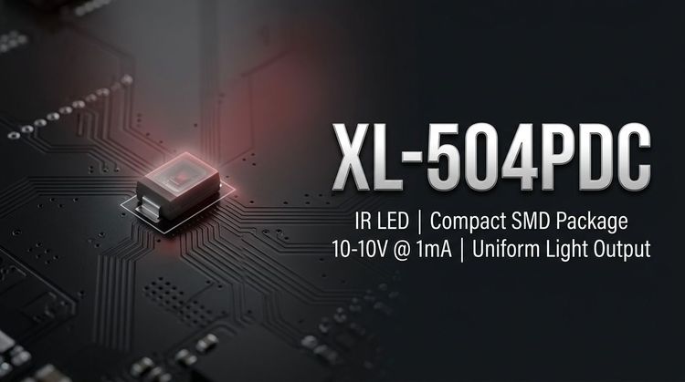
💡 The XL-504PDC is a discrete 5mm F5 infrared phototransistor designed for 940nm wavelength detection. 🚀 Unlike standard indicator LEDs, this component functions as a receiver unit, translating infrared light signals into electrical currents for processing systems. 👇 It features a black epoxy colloid to filter visible light interference, ensuring signal stability in ambient lighting conditions. 🔒 Designed for through-hole technology (THT) assembly, it provides a robust solution for applications requiring sensor integration on non-SMT PCBs or wire-ridged connections.
🎯 Typical Applications
- Industrial Control Systems: Used in counters, smart meters, and thermal imaging equipment requiring non-contact signal detection.
- Consumer Electronics: Essential component in infrared remote controllers for TVs and set-top boxes.
- Robotics & Automation: Integrated into intelligent cars and robotic sensors for obstacle avoidance and line tracking.
- Security & Surveillance: Utilized in camera monitoring heads for triggering signals or night-vision communication.
- Medical Devices: Implemented in equipment needing safe, wireless infrared data transmission or control.
- Wireless Communication: Facilitates short-range signal transmission between isolated circuits.
⚡ Key Technical Specifications
| Parameter | Symbol | Test Condition | Min / Typ / Max | Unit |
|---|---|---|---|---|
| Collector-Emitter Breakdown Voltage | $V_{(BR)CEO}$ | $I_C = 100\mu A$ | 30 / - / - | V |
| Emitter-Collector Breakdown Voltage | $V_{(BR)ECO}$ | $I_E = 100\mu A$ | 5 / - / - | V |
| Collector Saturation Voltage | $V_{CE(SAT)}$ | $I_C = 0.1mA$ | - / - / 0.8 | V |
| Collector Dark Current | $I_o$ | $V_{CE} = 10V$ | - / - / 100 | nA |
| On-state Collector Current | $I_{(on)}$ | $E_e = 1mW/cm^2$, $\lambda=940nm$ | - | mA |
| Rise Time | $t_r$ | $V_{CE}=5V, R_L=100\Omega$ | - / 3 / - | $\mu s$ |
| Fall Time | $t_f$ | $V_{CE}=5V, R_L=100\Omega$ | - / 3 / - | $\mu s$ |
📈 Note: Luminous intensity guarantees a simulated error of $\pm 15%$. Response times are critical for high-frequency signal transmission.
⚠️ Absolute Maximum Ratings & Process Limits
| Parameter | Symbol | Maximum Rating | Unit |
|---|---|---|---|
| Collector-Emitter Voltage | $V_{CEO}$ | 30 | V |
| Emitter-Collector Voltage | $V_{ECO}$ | 5 | V |
| Operating Temperature | $T_{opr}$ | -20 to +85 | °C |
| Storage Temperature | $T_{stg}$ | -40 to +85 | °C |
| Soldering (Reflow) | $T_{sol}$ | 240 | °C (≤6s) |
| Soldering (Manual) | $T_{sol}$ | 300 | °C (≤3s) |
🔒 Critical Design Warning:
- Pulse Handling: Ensure pulse width $\le 0.1ms$ and duty cycle $\le 1/10$ to prevent junction degradation.
- Lead Forming: Bending stress must be minimized; bend points must be at least 2.0mm away from the epoxy colloid base to prevent seal damage.
- Cleaning: Do not use harsh chemicals (Trichloroethylene, Acetone). Use Ethanol only for $<3$ minutes at room temperature.
📦 Package, Dimensions & Assembly Notes
- Package Type: F5 Round Radial Lead.
- Dimensions: Diameter $\approx 5.0mm$, Height $\approx 8.7mm$. Pitch and lead span adhere to EIA standard packaging.
- Moisture Sensitivity: Classified as MSL 2. Components must be stored in $<30^{\circ}C / <70%$ RH environments.
- Assembly:
👇 Support forming must use fixtures to ensure consistent pin spacing matching the PCB layout.
🚀 Soldering should occur after lead forming. Avoid applying mechanical pressure to the base once soldered to the PCB.
🏗️ Sourcing & Supply Considerations
- Packaging Standard: Components are supplied in moisture-proof and anti-electrostatic foil bags, often in bulk quantities for volume manufacturing.
- Authenticity Check: Verify the "XINGLIGHT" brand laser marking and confirm ROHS compliance certificates upon receipt.
- BOM Integration: Suitable as a drop-in replacement for standard 5mm phototransistors in 940nm systems, provided pin-out and voltage limits are observed.
- Sample Evaluation: Request binning data for light current ($I_{(on)}$) to ensure consistency in sensitivity across large batches.
❓ Frequently Asked Questions
Q: What is the operating wavelength range for the XL-504PDC?
A: The XL-504PDC is optimized for 940nm infrared light. It features a black colloid that filters out visible light, reducing noise from ambient sunlight or indoor lighting.
Q: Can this component be used for surface mount (SMT) assembly lines?
A: No, the XL-504PDC is a through-hole (THT) component with radial leads. It is designed for manual insertion or wave soldering processes, not reflow ovens (despite reflow temp ratings being provided for testing limits).
Q: What is the shelf life of the XL-504PDC?
A: The datasheet recommends using the components within 3 months of receipt if kept in the original packaging. For longer storage, use a dry box with desiccant or nitrogen.
Q: How do I prevent damage during the lead forming process?
A: Always use a professional fixture or jig. Ensure the bend point is at least 2mm away from the colloid body to avoid cracking the epoxy seal or stressing the internal wire bonds.
Q: What is the maximum switching speed I can achieve?
A: The typical rise and fall times ($t_r, t_f$) are 3$\mu s$. This supports signal switching up to approximately 100kHz, making it suitable for standard remote control protocols (NEC, RC5) but not for high-speed data fiber optics.