📌 Product Overview
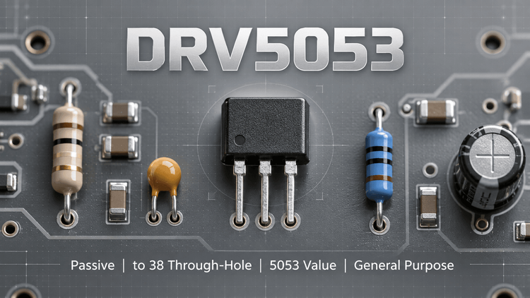
The DRV5053 is a chopper-stabilized linear bipolar Hall effect sensor from Texas Instruments. It outputs a ratiometric analog voltage (0.2 V to ~1.8 V, with 1 V at B = 0 mT) that responds linearly to magnetic flux density and distinguishes field polarity — unlike latching or switch-type Hall ICs, no digital threshold logic is involved.
It operates from 2.5 V to 38 V with no external regulator and includes reverse-supply protection to –22 V, load-dump tolerance to 40 V, and output short-circuit limitation.
💡 The most critical selection variable is the sensitivity suffix (OA through VA): seven grades from –11 mV/mT to –90 mV/mT determine your measurable field range. Choosing the wrong suffix cannot be fixed in firmware — it is a board respin.
🎯 Typical Applications & Design Context
- Flow meters — analog polarity-aware output maps directly to bidirectional flow tracking
- Damper controls and docking adjustment — linear output enables continuous position feedback, not just on/off detection
- Vibration correction systems — 35 µs fast power-on supports duty-cycled, low-power sensing
👇 Why it fits: the wide 2.5–38 V supply range allows direct connection to industrial rails (12 V, 24 V) without a regulator, and the analog output simplifies interface to an ADC compared to I²C sensors — fewer firmware dependencies, easier fail-safe diagnostics.
📊 Key Technical Specifications
| Parameter | Value |
|---|---|
| Output type | Ratiometric analog, 0.2 V – ~1.8 V |
| Output at B = 0 mT | 1 V (typ.) |
| Supply voltage | 2.5 V – 38 V |
| Sensitivity options | –11 (OA), –23 (PA), –45 (RA), –90 (VA), +23 (CA), +45 (EA), +11 mV/mT (other grades) |
| Sensitivity drift over temperature | ±10% (typical envelope) |
| Operating temperature | –40°C to +125°C (Q grade) |
| Power-on time | 35 µs |
| Output drive | 2.3 mA sink / 300 µA source |
⚠️ Note the ±10% sensitivity tolerance over temperature — this, not the nominal sensitivity, defines your system accuracy budget.
⚠️ Absolute Maximum Ratings & Process Limits
| Limit | Rating | Practical Consequence |
|---|---|---|
| Supply voltage (reverse) | –22 V | Below this, internal protection fails; reverse-wiring during harness assembly destroys the part |
| Load dump | 40 V | Automotive-like transients tolerated, but sustained overvoltage is not covered |
| Junction temperature (max) | 150°C | Exceeded during reflow if profile is too aggressive |
| Output | Short-circuit protected, current limited | Sustained short still heats the die |
🔒 Field-experience note: the –22 V reverse protection is genuinely robust, but only up to –22 V. In 24 V industrial systems with unregulated supplies or miswired harnesses, transient spikes beyond this limit are a real failure mode. Also verify your ADC input impedance: the output can only source 300 µA, so a heavy load will distort the linear range. If the output is pulled above VQ's headroom (the output never truly reaches 0 V or VCC), low-field readings near BMIN will saturate earlier than expected.
🧩 Package, Dimensions & Assembly Notes
| Package | Body Size | Mounting |
|---|---|---|
| SOT-23 (DBZ) | 2.92 mm × 1.30 mm | Surface mount, 3-pin |
| TO-92 (LPG) | 4.00 mm × 3.15 mm | Through-hole, 3-pin |
💡 The two packages are electrically identical but not footprint-compatible — pin order differs, so mechanical/magnetic alignment changes. For SOT-23: standard reflow profile, MSL handling per manufacturer data, no special thermal pad required. For TO-92: wave or hand solder; verify lead forming before automated insertion. Magnetic sensitivity axis is perpendicular to the package face — fix orientation in mechanical design early.
🔍 Procurement & Sourcing Insights
- Suffix is the BOM risk: DRV5053OA, PA, RA, VA, CA, EA are frequently mixed up in BOM data entry. A VA (–90 mV/mT) shipped instead of an OA will fail functional test silently on loose magnet designs. Verify the full ordering code, not just "DRV5053."
- Sample-to-production gap: TI samples are easy to obtain, but the suffix you validated must be locked into the BOM with the full part number including package and packaging option (tape/reel M vs. blank for TO-92).
- Alternative risk: pin-compatible Hall sensors exist, but few offer ±10% sensitivity stability over temperature at comparable price — re-validate the temperature drift curve, not just nominal gain.
- LDeepAI supports full code verification, datasheet cross-checks, and traceable channel sourcing for DRV5053 family parts — contact us for suffix-matching and stocking support.
❓ FAQ
Q1: Can I replace a DRV5053OA with DRV5053VA in the same footprint?
A: Electrically yes (same pinout, same output structure), but sensitivity differs by 8× (–11 vs. –90 mV/mT). Your measurable field range and ADC resolution mapping change completely. Treat them as different components.
Q2: Why does my output never reach 0 V or 2 V?
A: By design. The linear output spans approximately 0.2 V to 1.8 V. Systems expecting rail-to-rail analog output will clip at the field extremes.
Q3: Is an external voltage regulator needed on a 24 V rail?
A: No. The 2.5–38 V range covers 24 V systems directly, including typical load-dump transients up to 40 V.
Q4: SOT-23 vs TO-92 — can I dual-source both on one PCB?
A: No. Pin configurations and geometry differ. Choose one package at layout stage; the TO-92 suits wire-harness or probe assemblies.
Q5: How do I verify authentic TI parts from distribution?
A: Check date codes, full ordering suffix, and marking against TI's device nomenclature. LDeepAI performs incoming traceability and can supply from authorized or verified-stock channels.