📌 Product Overview
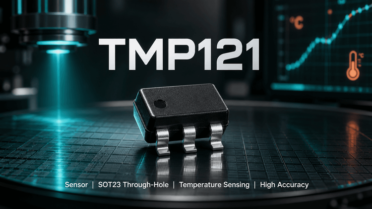
The Texas Instruments TMP121 is a digital temperature sensor designed for precision thermal management in space-constrained and power-sensitive systems. Utilizing a SPI-compatible interface, this component eliminates the need for complex analog circuitry by providing a direct 12-bit + sign temperature output. Housed in a tiny SOT23-6 package, it is specifically engineered for OEMs requiring reliable battery management and peripheral thermal protection in consumer electronics and industrial applications. For engineers, the critical selection variables are its low quiescent current (50µA max), which extends battery life, and its wide supply range (2.7V to 5.5V), ensuring compatibility with various MCU logic levels without additional regulators.
🎯 Typical Applications & Design Context
The TMP121 excels in applications where board real estate is at a premium and accurate thermal monitoring is critical for safety or performance.
- 📱 Battery Management Systems (BMS): 🚀 Monitors battery pack temperature to prevent overheating during charging/discharging cycles.
- 💻 Notebook Computers & Office Machines: 📈 Provides thermal protection for CPU cores, GPU peripherals, and power MOSFETs.
- 🔋 Portable Industrial Instrumentation: ✨ Suited for handheld devices where the 2.7V minimum supply voltage aligns perfectly with low-battery conditions.
- 📡 Communication Infrastructure: 👇 Used for monitoring RF power amplifier temperatures where wide ambient ranges are common.
The device is chosen over analog thermistors when the MCU lacks available ADC channels or when the BOM cost of external calibration components is prohibitive.
📊 Key Technical Specifications
| Parameter | Test Conditions | Min | Typ | Max | Unit |
|---|---|---|---|---|---|
| Temperature Accuracy | -25°C to +85°C | - | ±0.5 | ±1.5 | °C |
| Temperature Range | Operating | -40 | - | +125 | °C |
| Resolution | Digital Output | - | - | 0.0625 | °C |
| Supply Voltage | Operating Range | 2.7 | - | 5.5 | V |
| Quiescent Current | Serial Bus Inactive | - | 35 | 50 | µA |
| Conversion Time | 12-Bit | 240 | 320 | - | ms |
| Interface Protocol | - | - | SPI | - | - |
💡 Design Insight: While the datasheet claims accuracy up to 150°C, engineers should note that the ±1.5°C accuracy is only guaranteed from -25°C to +85°C. Readings at extreme ranges (up to 150°C) may drift beyond this tolerance window.
⚠️ Absolute Maximum Ratings & Process Limits
| Parameter | Rating | Unit | ⚠️ Failure Mechanism / E-E-A-T Note |
|---|---|---|---|
| Supply Voltage (V+) | 7.0 | V | Exceeding 7V causes immediate oxide breakdown of the input transistors. |
| Input Voltage | -0.3 to +7 | V | Negative voltage clamping currents can cause latch-up in mixed-signal environments. |
| Junction Temp (Tj) | +150 | °C | Critical: Internal accuracy degrades rapidly above 125°C. Do not rely on specific numerical accuracy for safety triggers near 150°C. |
| Lead Temp (Soldering) | +300 | °C | SOT23-6 is thermally robust, but >10s exposure beyond 260°C (reflow) risks delamination. |
| Storage Temp | -60 to +150 | °C | Moisture ingress is a risk; MSL rating usually 3 (needs bake if exposed >168hrs). |
⚡ E-E-A-T Comment: During wave soldering or rework, localized heating of the SOT23-6 package can temporarily shift the sensor's zero-point. Allow the board to thermally stabilize (approx. 2 minutes) before performing critical calibration reads after any high-heat process.
🧩 Package, Dimensions & Assembly Notes
- Package Type:SOT23-6 (Tiny Surface Mount).
- Footprint Caution: ⚠️ Pin 1 orientation differs slightly between common SOT23-6 layouts. TI datasheet specifies Pin 1 is "Top Left" with marking in specific orientation. Cross-reference the PCB silkscreen with the package drawing "T121" marking to avoid 180° rotation errors during assembly.
- Thermal Resistance (θJA): 200°C/W (Surface Mount). This indicates the package self-heats slightly under high current.
- NC Pins: Pins labeled NC (No Connection) must be left floating or connected to GND. Do not leave them floating as "stubs" near high-speed traces to prevent noise coupling.
- SMT Land Pattern: Standard SOT23-6 stencil design applies. No special thermal relief is usually needed due to low power dissipation (<1mW).
🔍 Procurement & Sourcing Insights
- Supply Chain Risk: As a legacy part (originally released 2003), lead times can fluctuate. Check the "Last Time Buy" (LTB) or "Not Recommended for New Designs" (NRND) status with TI distributors before high-volume design lock-in.
- Alternative Validation: 🚀 When validating alternatives (e.g., from Microchip or NXP), verify the SPI timing polarity (CPOL/CPHA). The TMP121 specific clock edge requirements must match your MCU driver or the readout will be garbage.
- Counterfeit Warning: 🚗 Common gray-market failure involves re-marked TMP123 (different pinout) sold as TMP121. Always verify "T121" vs "T123" laser marking under magnification upon receipt.
- MOQ & Samples: Typically available in cut-tape (low MOQ) from major distributors, simplifying prototyping phases.
❓ FAQ
Q: Can the TMP121 be used as a direct replacement for an NTC thermistor?
A: Functionally yes, but physically and electrically different. The TMP121 outputs digital SPI data, whereas an NTC is a resistor divider (analog). You cannot replace the component without changing the MCU firmware and removing the pull-up resistor/ capacitor network used for the NTC.
Q: What is the difference between TMP121 and TMP123?
A: They are pin-to-pin compatible but have different internal register configurations or package markings. Always verify the specific laser marking ("T121" or "T123") and re-check the pin configuration in the latest datasheet, as connecting them incorrectly yields wrong temperature data.
Q: Does the low supply current include the current consumed by the SPI bus?
A: No. The 50µA spec is for "Quiescent Current" (Serial Bus Inactive). When actively reading data via SPI (SCK switching), the current draw will spike momentarily. Ensure your LDO can handle these transient spikes if polling rapidly.
Q: How do I handle the NC pins on the SOT23-6 package?
A: Datasheet states: "Pins labeled NC should be left floating or connected to GND." Best practice for mass production is to connect them to GND (Ground) to prevent noise coupling and stabilize the PCB during wave soldering.