📌 Product Overview
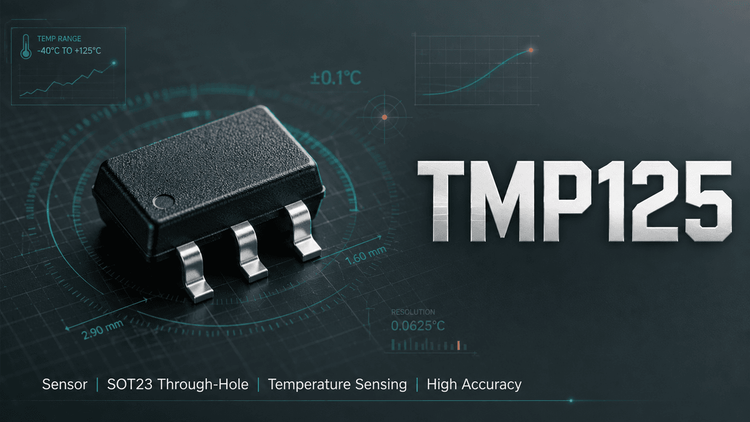
The TMP125 from Texas Instruments is a 10-bit digital temperature sensor with an SPI-compatible interface, packaged in a tiny SOT23-6. It measures −40°C to +125°C with ±2.0°C max accuracy (−25°C to +85°C), requires no external components, and draws only 50µA max.
The critical selection variables for engineers are interface choice (SPI vs. I²C alternatives), the 0.25°C resolution, and the 120ms update rate—which dictates whether the TMP125 suits your thermal polling architecture.
🎯 Typical Applications & Design Context
💡 The TMP125 fits designs where board space and power budget dominate:
- Base station and telecom equipment — wide supply range (2.7–5.5V) tolerates noisy rails
- Notebook and peripheral thermal protection — SOT23-6 fits tight PCB real estate near heat sources
- Data acquisition systems — SPI simplifies integration with MCU-heavy architectures
👇 Note the related-product landscape: if your firmware team prefers I²C, the TMP100/101 or TMP75/175 are the designated TI cross-picks; the TMP121/123 offer 1.5°C accuracy on SPI. Choosing TMP125 means accepting ±2.0°C accuracy in exchange for cost and simplicity.
📊 Key Technical Specifications
| Parameter | Condition | Value |
|---|---|---|
| Accuracy | −25°C to +85°C | ±0.5°C typ / ±2.0°C max |
| Accuracy | −40°C to +125°C | ±1.0°C typ / ±2.5°C max |
| Resolution | — | 10-bit (0.25°C) |
| Supply range | — | 2.7V to 5.5V |
| Quiescent current | 25°C, bus idle | 36µA typ / 50µA max |
| Shutdown current | — | 0.1µA typ / 1µA max |
| Conversion / update rate | 10-bit | 60ms / 120ms |
| Logic levels | — | VIH ≥ 0.7(V+), VIL ≤ 0.3(V+) |
✨ The 120ms update rate is the parameter most often overlooked—systems polling faster than ~8Hz will read stale data.
⚠️ Absolute Maximum Ratings & Process Limits
| Rating | Limit |
|---|---|
| Supply voltage | +7V |
| Input voltage (any pin) | −0.3V to +7V |
| Input current | ±10mA |
| Lead soldering temperature | +300°C |
| Junction temperature | +150°C |
| Storage temperature | −60°C to +150°C |
| ESD (HBM / CDM) | 4000V / 1000V |
🔒 E-E-A-T field note: As a precision analog IC, the TMP125 is ESD-sensitive in ways that don't show up as hard failures—a sub-lethal HBM event can shift accuracy by fractions of a degree, silently breaking your ±2.0°C spec. In Huaqiangbei-channel sourcing, devices that passed a multimeter "it works" test may still be degraded. Insist on ESD-safe handling and documented MSL/lot traceability. Also note thermal resistance θJA of 200°C/W in SOT23-6: self-heating from adjacent hot components will read as ambient error.
🧩 Package, Dimensions & Assembly Notes
- Package: SOT23-6 (DBV), pin-marking "T125"; Pin 1 (GND) determined by package-marking orientation—verify reel orientation before loading feeders
- No external components required — decoupling per standard practice (100nF close to V+)
- Pinout: GND/SI/V+ on left; SCK/CS/SO on right—watch SI (Pin 2) vs. SO (Pin 6) confusion during footprint review
- Soldering: lead temperature limit 300°C; standard lead-free reflow profiles are acceptable, avoid extended dwell above 260°C
- Layout: θJA of 200°C/W means minimal copper spreading; place away from power devices to avoid measurement bias
🔍 Procurement & Sourcing Insights
- Lifecycle risk: The TMP125 is a mature 2004-era part; verify TI's active/status status before committing long-term BOM positions—last-time-buy windows matter.
- Counterfeit exposure: SOT23-6 marking ("T125") is easily remarked; insist on authorized-channel or full traceability.
- Alternatives: TMP121/123 are SPI drop-in-class upgrades (1.5°C) but not pin-identical—validate footprint and CS/timing polarity before substitution.
- 👇 LDeepAI provides verified TI-channel sourcing, sample support, and batch-level traceability for TMP125—reach out for MOQ and lead-time confirmation.
❓ FAQ
Q: Can I replace TMP125 with TMP75 (I²C) without layout change?
A: No. Different interface (I²C vs SPI) and different pinout in SOT23-6. Firmware and PCB changes are required; this is a redesign, not a drop-in.
Q: Why do TMP125 readings drift 1–2°C on my board?
A: Likely self-heating or adjacent heat sources. θJA is 200°C/W; 10mW dissipation adds ~2°C. Also check SPI timing—reading during conversion returns stale data.
Q: Is ±2.0°C accuracy guaranteed over the full range?
A: No. ±2.0°C max applies only from −25°C to +85°C; beyond that, the limit widens to ±2.5°C. Systems specifying tighter tolerance should evaluate TMP121/123.
Q: What's the minimum SPI clock speed?
A: The datasheet doesn't specify a minimum clock; the 60ms conversion time and 120ms update rate define read pacing, not SCK frequency limits.
Q: How do I verify authentic TMP125 from open-market suppliers?
A: Check date-code consistency, marking laser quality, and request lot traceability. Functional testing alone cannot detect accuracy degradation from ESD or re-marked parts.