
Specifications
| Type | Description |
|---|---|
| Part Number | XL-JY2012UYC-11 |
| Manufacturer | XINGLIGHT |
| Product Type | SMD LED |
| Category | LED |
| Package / Case | SMD LED, 2.0 x 1.2 x 1.1 mm |
| Outline Dimensions | 2.0 x 1.2 x 1.1 mm; L/W/H |
| Luminous Color | Yellow; transparent/water colloid |
| Moisture Sensitivity Level | MSL 3 |
| Maximum Power Dissipation | 60 mW; Ta=25°C |
| Maximum Continuous Forward Current | 30 mA; Ta=25°C |
| Peak Forward Current | 80 mA; pulse width <=0.1 ms, duty <=1/10, Ta=25°C |
| Maximum Reverse Voltage | 5 V; Ta=25°C |
| ESD Rating | 2000 V; antistatic ability |
| Operating Temperature Range | -40 to +85 °C; Ta=25°C absolute maximum rating table |
| Storage Temperature Range | -40 to +85 °C; Ta=25°C absolute maximum rating table |
| Lead Soldering Temperature and Time | 260°C, <=6 s; absolute maximum rating |
| Luminous Intensity | 80 to 210 mcd; IF=20 mA, Ta=25°C |
| Dominant Wavelength | 585 to 595 nm; IF=20 mA, Ta=25°C |
| Peak Wavelength | 590 nm typ; IF=20 mA, Ta=25°C |
| Forward Voltage | 1.9 to 2.4 V; IF=20 mA, Ta=25°C |
| Viewing Angle | 120° typ; 2θ1/2, IF=20 mA, Ta=25°C |
| Half Wave Width | 20 nm typ; IF=20 mA, Ta=25°C |
| Reverse Current | <=1 µA; VR=5 V, Ta=25°C |
| Brightness Bin D2 | 80 to 120 mcd; IF=20 mA |
| Brightness Bin D3 | 120 to 150 mcd; IF=20 mA |
| Brightness Bin D4 | 150 to 180 mcd; IF=20 mA |
| Brightness Bin D5 | 180 to 210 mcd; IF=20 mA |
| Brightness Tolerance | ±10%; brightness grading |
| Forward Voltage Bin M18-1 | 1.9 to 2.0 V; IF=20 mA |
| Forward Voltage Bin M18-2 | 2.0 to 2.1 V; IF=20 mA |
| Forward Voltage Bin M18-3 | 2.1 to 2.2 V; IF=20 mA |
| Forward Voltage Bin M18-4 | 2.2 to 2.3 V; IF=20 mA |
| Forward Voltage Bin M18-5 | 2.3 to 2.4 V; IF=20 mA |
| Voltage Tolerance | ±0.1 V; voltage grading |
| Dominant Wavelength Bin HY03 | 585 to 587.5 nm; IF=20 mA |
| Dominant Wavelength Bin HY04 | 587.5 to 590 nm; IF=20 mA |
| Dominant Wavelength Bin HY05 | 590 to 592.5 nm; IF=20 mA |
| Dominant Wavelength Bin HY06 | 592.5 to 595 nm; IF=20 mA |
| Wavelength Tolerance | ±1 nm; wavelength grading |
| Default Test Environment Temperature | 25 ±5°C; unless otherwise indicated |
| Hand Soldering Iron Power | <30 W; hand soldering recommended only for repair/rework |
| Hand Soldering Temperature | <300°C; each terminal once only |
| Hand Soldering Time | <3 s; per terminal, one time only |
| Maximum Reflow Cycles | 2 times; reflow soldering |
| Recommended Maximum Soldering Temperature | 240 ±15°C for 6 s; product maximum welding temperature recommendation |
| Post-Opening Floor Life | 168 hours / 7 days; stored at <=30°C and <=40% RH after opening |
| Baking Condition | 60 ±5°C for 24 hours; if desiccant/package fails or storage time exceeded |
| Datasheet Status | request_only |
Product Overview
The XL-JY2012UYC-11 is a XINGLIGHT yellow SMD chip LED with transparent/water colloid construction and a compact 2.0 x 1.2 x 1.1 mm outline. It is categorized as an LED and is specified with MSL 3 moisture sensitivity for handling and assembly planning.
At IF=20 mA and Ta=25°C, the LED provides 80 to 210 mcd luminous intensity, a 585 to 595 nm dominant wavelength, 590 nm typical peak wavelength, and 20 nm typical half wave width. Forward voltage is specified from 1.9 to 2.4 V, reverse current is <=1 µA at VR=5 V, and the typical viewing angle is 120°.
Absolute maximum ratings include 60 mW power dissipation, 30 mA continuous forward current, 80 mA peak forward current under pulsed conditions, and 5 V maximum reverse voltage. The operating and storage temperature ranges are both -40 to +85°C. Assembly guidance includes up to 2 reflow cycles, 240 ±15°C for 6 s recommended maximum soldering temperature, and 260°C for <=6 s lead soldering limit.
Key Features
- Yellow SMD chip LED with transparent/water colloid construction
- Compact 2.0 x 1.2 x 1.1 mm outline
- 80 to 210 mcd luminous intensity at 20 mA
- 585 to 595 nm dominant wavelength range
- 590 nm typical peak wavelength at 20 mA
- 1.9 to 2.4 V forward voltage range
- 120° typical viewing angle for wide indication
- 30 mA maximum continuous forward current
- MSL 3 moisture sensitivity level
- -40 to +85°C operating temperature range
Typical Applications
- Yellow status indicators
- Compact panel indication
- PCB-mounted visual alerts
- Small display marker lights
- Equipment mode indication
- Control board signal indication
Procurement Notes
When requesting a quote for XL-JY2012UYC-11, buyers should confirm the manufacturer, package or case, required quantity, target date code, compliance documents, packing method, destination country and expected delivery schedule.
If alternatives are acceptable, buyers should share the approved vendor list, required electrical or optical limits, package constraints and qualification requirements. Any alternative part should be reviewed by the buyer's engineering team before production use.
For LED and optoelectronic sourcing, brightness bin, wavelength or color temperature bin, forward voltage range, viewing angle, moisture sensitivity level and soldering process limits may affect final selection, availability and lead time.
Related Technical Articles
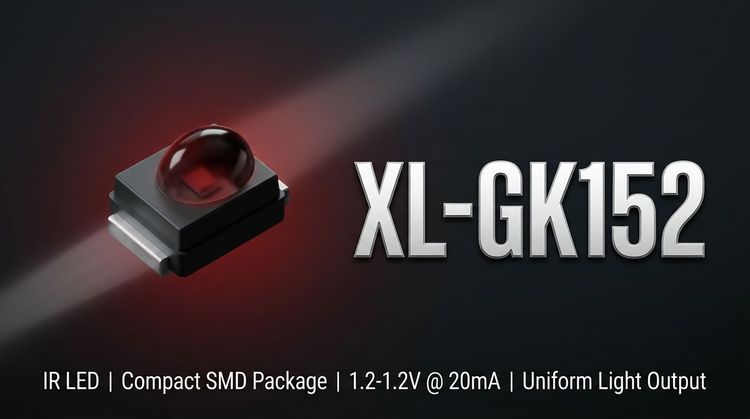
XL-GK152 Through-Beam Sensor: Thermal & Signal Drift Analysis
The XINGLIGHT XL-GK152 is a 940nm through-beam photoelectric switch designed for high-reliability object detection in compact OEM circuits. This technical analysis evaluates cri...
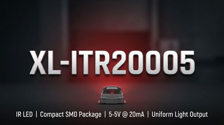
XL-ITR20005 Transmissive Sensor: SMT Integration & Signal Consistency
The XL-ITR20005 from XINGLIGHT is a transmissive photoelectric switch designed for compact automation and consumer electronics, utilizing a 940nm infrared emitter and phototrans...
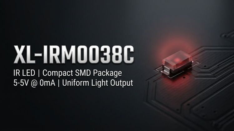
XL-IRM0038C IR Receiver: Evaluating 37.9kHz Immunity & SMT Integration
The XL-IRM0038C from XINGLIGHT is a LED designed for indicator and backlight applications. This technical guide helps design engineers and procurement teams evaluate the compone...
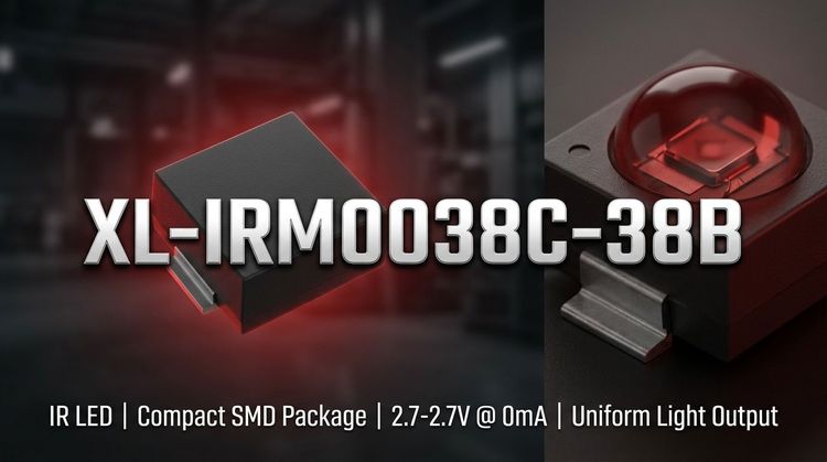
XL-IRM0038C-38B SMD LED — Technical Specifications & Design Guide
The XL-IRM0038C-38B from XINGLIGHT is a LED designed for indicator and backlight applications. This technical guide helps design engineers and procurement teams evaluate the com...
FAQ
What package size does XL-JY2012UYC-11 use?
XL-JY2012UYC-11 uses an SMD LED package with 2.0 x 1.2 x 1.1 mm outline dimensions, specified as length, width, and height in the extracted datasheet facts.
What optical output is specified at 20 mA?
At IF=20 mA and Ta=25°C, the device is specified for 80 to 210 mcd luminous intensity, 585 to 595 nm dominant wavelength, 590 nm typical peak wavelength, and 120° typical viewing angle.
What soldering limits apply to this LED?
The absolute maximum lead soldering limit is 260°C for <=6 s. The recommended maximum soldering temperature is 240 ±15°C for 6 s, with a maximum of 2 reflow cycles.
Technical Review & Sourcing Note
Prepared by LDeepAI Component Sourcing Team. Reviewed for RFQ, documentation and alternative sourcing use. Last updated: July 3, 2026.
This page is based on manufacturer datasheet information and LDeepAI sourcing review. Specifications should be verified against the official manufacturer datasheet before final procurement or design approval. Final electrical, optical and reliability approval should be confirmed by the buyer's engineering team.